|
|
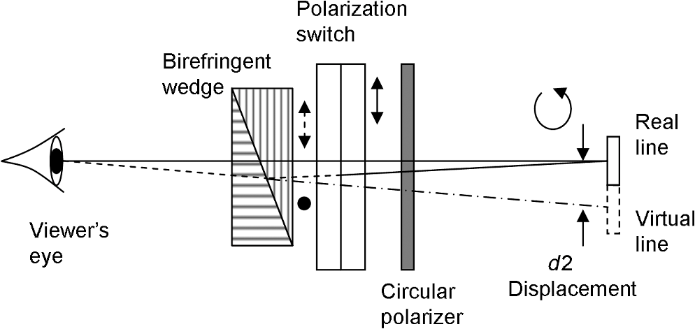
1.IntroductionA large share of recently manufactured LCD televisions (TVs) is capable of displaying stereoscopic three-dimensional (3-D) content. Two types of stereoscopic TVs dominate the consumer market, one based on shutter glasses (SGs) and the other on film patterned retarders (FPRs). Both SG and FPR TV systems are not entirely free of disadvantages. They simply combine relatively low manufacturing complexity and low cost. An SG stereoscopic TV system provides full-resolution stereoscopic images. It is based on time-sequential displaying of left and right images followed by synchronous blocking of the right and left eyes by the corresponding shutter of the SG. To provide low crosstalk stereoscopic images without visible ghosting the LCD display incorporates an image panel with a short response time and a backlight unit, operating in a short-pulse blinking mode.1 Usually, the LCD panel of an SG system features an increased frame rate at least 100 to 120 Hz in order to reduce visible image flicker. However, the presence of a bright light source inside the viewing field of the SG can cause perceivable flicker. An FPR system is based on displaying stereoscopic images in a row-interleaved mode, coding of odd and even rows with an alternating polarization of emitted light, and decoding by passive polarized glasses. Coding is provided by a stripe-patterned anisotropic retarder film bonded on the output surface of the panel. Ideally, the patterned retarder should be placed directly in the color filter plane, but in fact the film is placed on the outer surface of the LCD substrate, i.e., at certain distance from the pixel lines. The presence of this nonzero distance causes an effect, when good stereo with minimum ghosting can be seen only within a limited viewing zone. In order to increase the viewing zone the stripes with different optical retardation are separated from each other by opaque (black) stripes.2 The main disadvantage of FPR technology is the reduction of vertical resolution of stereoscopic images by the factor of 2. As could be seen, both systems are not free of certain disadvantages. The first type of TV system features full-resolution imaging, but it requires active glasses and it is not entirely free of flicker. The second type is flicker-free and uses passive glasses, but it reduces the vertical resolution by the factor of 2. A TV system combining flicker-free operation and full resolution could be of great interest. 2.BackgroundFlicker-free operation of a time-sequential 3-D stereo TV can be achieved by modifying an SG. Recently we developed an SG, which does not produce flicker from ambient light sources.3 This paper is focused on a different concept using a combination of active glasses and a patterned retarder. Some attempts to get rid of both flicker and reduction of resolution by combining two stereoscopic technologies can be found in the literature.4,5 Instead of passive glasses, the researchers applied no-flicker retardation-switching glasses together with a patterned retarder. This kind of glasses can be made by removing the front polarizer in a conventional SG. The glasses are switchable between blocking the polarized light, emitted by odd image lines, and blocking orthogonally polarized light, emitted by even image lines. This allows for displaying full-resolution stereoscopic image within two sequential frames. Since the averaged screen luminance in odd and even frames remains the same, and ambient light is assumed as nonpolarized, the glasses do not produce visible flicker. A full-resolution image is displayed within two sequential frames. In the first frame, the display shows only odd lines of the left image and even lines of the right image. In the second frame, even lines of the left image and odd lines of the right image are shown. Due to the synchronous switching of the eyeglasses, left and right eyes of the viewer perceive full-resolution left images and full-resolution right images, respectively, displayed in an interlaced manner. Note that each line of the image panel displays the lines of the left image and the lines of the right image in a sequence. Therefore dynamic crosstalk problems, inherent in conventional LCD TVs with SG are also present in the system with retardation-switching glasses. Imperfections in the FPR usually causes a rather low level of static crosstalk; however, in the reported TV architecture increased static crosstalk occurs.4 Considering the small amount and different physical nature of dynamic crosstalk and static crosstalk in retardation-switching 3-D TVs it could be expected that the resultant crosstalk would be the sum of two individual crosstalks. Finally, the method has demonstrated 5% of the crosstalk between the left and right channels4 whereas normally the crosstalk of either FPR TV or SG TV does not exceed 1%. A high level of crosstalk produces visible image ghosting, reducing the overall fidelity of the displayed 3-D images. We have devised a new type of flicker-free active glasses and a full-resolution stereoscopic TV based on these glasses. Although the proposed 3-D TV system incorporates both FPR technology and time-sequential operation, it does not have any additional crosstalk compared to conventional FPR TVs. 3.Three-Dimensional Television System: Optical Architecture and Principle of OperationIn the system, based on retardation-switching glasses,4 odd lines of the display are used to display the left image lines within the first field and the right image lines within the second field. Since LCD cells cannot be switched between the left and the right image immediately, special measures are needed to reduce time sequential (i.e., dynamic) crosstalk to an acceptable level. According to the new concept, to exclude crosstalk, inherent in time-sequential LCD, any arbitrary row of the display panel should always display the left image or always display the right image. For example, odd display rows display odd image lines of the left image during a given frame, and even image lines of the left image during the next frame. The structure of the proposed TV system is shown in Fig. 1. Left–right image separation in the system is provided by a combination of FPR attached to the LCD panel (FPR panel) and polarizing filters, incorporated in the glasses. This combination can display stereo images with just one-half full vertical resolution. For example, the left viewer’s eye can see the light emitted only by the odd lines of the panel with dark spaces instead of the even lines. In order to provide full-resolution stereoscopic imaging, additional optics, capable of switchable refraction, is placed between each of two polarizing filters and the viewer’s eye. Fig. 1Proposed full-resolution stereoscopic system with active refraction glasses and film patterned retarder (FPR).  An optical element with switchable refraction provides periodic vertical displacement of the visual position of the TV screen in synchrony with the frame update. The required amount of displacement is one-half of the FPR lines’ pitch. In other words, active glasses provide frame-synchronized vibration of the visual axis. These two angularly displaced visual axes are shown in the drawing with solid and dashed lines. Actually, odd and even fields in each (left or right) image channels are displayed in sequence by the same physical lines of the image panel. However, the sequential images on the retina of human eye appear mutually displaced in the vertical direction due to the synchronous vibration of the visual axis provided by the active glasses. The lines of the odd image fields appear exactly between the lines of the even fields filling the spaces between them with missing image lines. Sequentially displayed sets of odd and even lines are perceived as full-resolution image due to the persistence of human vision. If sufficiently fast switching of the LCD cells is not possible, artifacts may appear even in static images. However, these switching artifacts would not look like well-known stereoscopic ghosting, caused by the same reason. Figure 2 shows the difference in appearance between conventional stereoscopic ghosting and the new system’s artifacts. Fig. 2Appearance of time-sequential image artifacts: (a) in previous technique and (b) in a new technique. 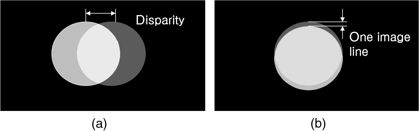 Figure 2(a) shows an image of a simple object (a white disk on a black background) in the presence of crosstalk with another eye image, exhibiting a given horizontal disparity. In conventional time sequential LCD displays with switching artifacts, the viewer can see a gray ghost image, horizontally displaced in accordance with the disparity. Usually, the disparity is much greater than the pixel pitch; otherwise the image looks flat. The human visual system is very sensitive to crosstalk in stereoscopic systems. A high level of ghosting causes difficulty in achieving stereoscopic fusion6 and can cause visual discomfort. Figure 2(b) shows the appearance of a similar image artifact in the proposed system. The artifact also can be described as a ghost image, slightly displaced in the vertical direction. However, the amount of the displacement is so small (one image line) that the presence of such ghost may not always be detected by the viewer. In this brief description of the proposed stereoscopic system we have to note that not only is the TV screen visually vibrating. Visual positions of all the objects, visible through the switchable refraction glasses, also perform a very small periodical displacement. It can be assumed that the displacement at one image line is not sufficiently large to bring noticeable discomfort to the viewer. 4.Beam Displacers and Other Components of the Glasses4.1.Beam Displacer Based on a Double-Refractive PlateThe required controllable displacement of the visual axis can be achieved using a combination of a polarization switch and crystal plate capable of double refraction. Double refraction is a widely known effect found in birefringent crystals like calcite. An example of double refraction is shown in Fig. 3. As can be seen, the image, visible through the crystal, is doubled. Image doubling occurs because each ray of unpolarized natural light is split inside the crystal into two orthogonally polarized rays, travelling in slightly different directions. One of the two linearly polarized light rays travels as ordinary light. Propagation of another light ray is different and it is responsible for the second image, displaced against the first one. This light ray is usually referred to as the “extraordinary” ray. By appropriate control of the incoming light polarization, the viewer can switch between the displaced and undisplaced images. In other words, a birefringent crystal combined with polarization switch for polarization control can be used as a beam displacer. To provide selective vision of the left and right images by the left and right eyes, respectively, we must combine the beam displacer with the same circular polarizer as is applied in conventional passive polarized glasses. A circular polarizer is simply a combination of a quarter-wave film and a linear polarizer. Figure 4 shows the resulting structure of the left eye filter. The first (from the right) element of the structure is the circular polarizer, which blocks incorrect input polarization. The second element is a polarization switch, comprising exactly the same liquid-crystal cell as is employed in conventional SG. The third element is the double-refraction plate. Light rays in the drawing are shown with solid and dashed lines. Double-sided arrows indicate vertical polarization of light whereas the black dot indicates horizontal polarization. Assume that odd rows of the display emit left circularly polarized light. A circular polarizer converts the left circularly polarized light into linearly (vertically) polarized light and blocks right circularly polarized light. A polarization switch either does not change the initial light polarization or rotates it by 90 deg depending on whether there is high or low voltage applied to the liquid-crystal cell. A double-refraction plate directs the light beam along one of two possible routes depending on the light polarization. If the light is polarized as an ordinary ray (horizontal in the picture) its route is not disturbed (shown by solid line); the viewer sees the TV screen and the displayed image lines in their real positions. If the light is polarized as an extraordinary beam (vertical in the picture), the light beam is refracted (shown by the dashed line) such that the light, incident to the eye pupil, comes from the inclined direction. Correspondingly, the viewer sees the image line in a virtual position, displaced vertically at a distance . The corresponding direction is shown in Fig. 4 by the dash–dot line. Also, the visual positions of all the visible objects appear displaced by the same distance . Sequentially displaying odd and even lines of the left image by the same odd row of the display pixels and synchronously changing the voltage, applied to the polarization switch, one can deliver a full-resolution image to the eye’s retina in an interlaced manner. The structure and operation of the right eye filter are similar to that described previously. The only difference is that the right circularly polarized light from even rows of the display is converted into vertically polarized light, and left circularly polarized light is blocked by the polarizer. Additionally the birefringent plate can be rotated by 180 deg around the view axis in order to change the direction of the displacement. The displacement between ordinary and extraordinary rays depends on the level of birefringence of the crystal, and the angle between the axis of the crystal and the optical axis of the plate. A formula for displacement of the plate , comprised of a single-axis anisotropic crystal, can be found in the literature7 where and are the ordinary and extraordinary refractive indexes, respectively, is the angle between the axis of the crystal and the optical axis, and is the thickness of the plate. As can be seen, the displacement is proportional to the thickness of the crystal and proportional to the birefringence (). Double refraction in a single-axis crystal plate does not occur if the plate surface is perpendicular or parallel to the crystal axis . That is why the displacement in accordance with Eq. (1) reaches a maximum value at a specific angle . Assuming application of the displacer as a filter of the eyeglasses, it is desirable to minimize the thickness of the displacer for a given displacement by setting . The corresponding expression for the minimum thickness is given byTo reduce the thickness of the birefringent plate one must use crystals with higher birefringence. The number of possible choices for a birefringent crystal is limited by the requirements that the crystal is colorless and can be grown in a size that is in accordance with the eyeglasses filter. Examples of available crystals with high birefringence are as follows: calcite (), yttrium ortho-vanadate (), and lithium niobate. Formally, liquid-crystals also could be considered potentially useful materials because of their high birefringence. The plate thicknesses calculated in accordance with Eq. (2) for the displacement 0.53 mm are shown in Table 1. Table 1Required thickness of the plate vs. the applied birefringent material.
As can be seen, the required plate thickness could be rather large despite the application of an anisotropic crystal with high birefringence. At a minimum, the plate would be much thicker than a conventional SG filter (about 1 mm). We fabricated birefringent plates from calcite with dimensions . Similar technology of doubling the image resolution with a help of a double-refraction optical plate has been disclosed by Fergason8 in his patent in 1998. In accordance with the cited patent the birefringent plate is placed directly on the display’s screen. Apparently, the plate size should be sufficiently large to cover the entire screen. To our knowledge commercially available plates with high birefringence do not exceed one decimeter square, and therefore they can cover only a very small screen. It was not apparent that similar technique could be applied in eyeglasses. Ray tracing, shown in Fig. 4, indicates that a similar resolution-doubling effect can be achieved using a birefringent plate incorporated in active glasses. In contrast with Fergason’s solution, the proposed technique does not lead to a limitation in screen size. However, the necessity of using a rather thick plate of crystalline material with high birefringence renders the glasses too heavy and expensive for applications in consumer TVs. To overcome the problem we have developed another type of beam displacer—a displacer based on birefringent wedges. 4.2.Beam Displacer Based on Birefringent WedgesAn appropriate combination of birefringent wedges is similar to the well-known Rochon prism and Wollaston prism. Both prisms are composed of two components, at least one of which is comprised of a birefringent material. A Rochon prism does not refract an ordinary polarized beam yet refracts an orthogonally polarized beam at a given angle. A Wollaston prism refracts both polarizations symmetrically in opposite directions (up and down in our case). Work pertinent to a Rochon-type wedge in active glasses is shown in Fig. 5. Birefringent wedges in Fig. 5 do not change the propagation of vertically polarized light, whereas horizontally polarized light is steered at a given angle. Unlike a birefrigent plate, described previously, the prism imparts tilt to the visual axis instead of parallel displacement. Other aspects of the system operation are similar to those described in the previous section. The tilt of the vision axis depends on the wedge design and the birefringence of the used material. The larger the birefringence of the wedge material () and the wedge angle , the larger the tilt angle. Lnear displacement of the line-of-vision increases in accordance with the distance to the image panel. The displacement of the glasses can be calculated as follows: where is the wedge angle, and is the distance to the screen (viewing distance).The distance of observation in Eq. (3) can be as long as 1500 to 3000 mm. Since the multiplier in the equation is large, the required displacement can be achieved with moderate birefringence () and small wedge angle . The smaller the required wedge angle, the thinner and lighter the wedge can be. We employed wedges, comprised of crystalline quartz, with dimensions and the total thickness of two wedges is 2.3 mm. The thickness of the wedges can be reduced even further if a birefringent material with higher birefringence is applied. A polymerized liquid-crystal which has already found applications in switchable microlens arrays9 may be a promising birefringent material for birefringent wedges. Applications of a highly birefringent liquid-crystal material allows for further reduction of the wedge thickness to about 0.05 mm. As can be seen, wedge-type birefringent elements can be made extremely thin due to the fact that the displacement depends on the viewing distance. On the other hand, the dependence of the linear displacement on the viewing distance is a disadvantage because the best viewing performance can be achieved only at the optimum viewing distance. To obtain the interval of “viewer’s freedom” we ran a simulation of possible image distortion for various viewing distances. The results of the simulation are shown in Fig. 6. In the simulation it was assumed that there were 25% opaque lines between the FPR stripes. At an optimum viewing distance the even image lines are seen exactly in the middle between the odd lines. Black lines between odd and even lines appear because of opaque stripes on the FPR. As the viewer moves closer to the TV screen the displacement decreases and the placement of the even lines becomes asymmetrical (). At a shorter viewing distance the even lines partially overlap with the even lines. In the regions where two consequently displayed white pixels overlap each other, the viewer perceives a brighter image (, ). At zero distance the effect of glasses disappears and the viewer can see simply a half-resolution image (). Fig. 6Visual distortion of the displayed letter N at various viewing distances : (a) ; (b) ; (c) ; (d) ; and (e) . 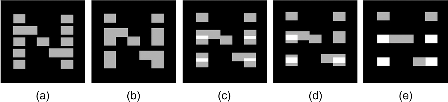 If the viewer moves further from the TV screen within the range , the image distortion behaves in a manner similar to that presented previously with the only difference that the even lines move up. At a longer distance, the even lines are placed between incorrect odd lines that can lessen the quality of fine details in the displayed image. As seen from the simulation, improvement in image resolution occurs within the full range ; however, the best results can be achieved within the narrower range . 5.Experimental ResultsWe have fabricated eyeglasses with switchable displacement of both types described in Sec. 4. The glasses are based on a standard Samsung SG frame and components. Front linear polarizers of the shutters in SG have been replaced with left circular or right circular polarizers. The output polarizers of the shutters have been replaced with a birefringent beam displacer. The modified eye-glasses are shown in Fig. 7. Fig. 7Active eyeglasses with switchable refraction: (a) eyeglasses with plate-type displacer and (b) eyeglasses with prism type displacer.  The FPR was laminated on a Samsung full high definition 3-D TV panel by “Arisawa” (Japan). A first qualitative system test confirmed that the active displacement glasses do not produce flicker because the work of the displacer does not change visible screen luminance. It can be assumed that the periodical displacement of all the objects in the visual field gives some undesirable image blur or contour-doubling, similar to those shown in Fig. 3. However, we did not detect any distracting effect of the new eyeglasses, probably because the displacement is rather small. During more detailed experiments, it was found that the plate-type displacer produces visible doubling of contours at very short distances to the object and essentially does not insert visual distortion at long distances. The wedge-type displacer, in contrast, does not change the appearance of close objects but doubles the contours of far-away objects. However, the effect of doubling is perceived as very small. At a viewing distance equal or shorter than 2 m, the effect of doubling vertical resolution provides much better image quality than conventional FPR 3-D TV. Figure 8(a) shows a magnified image of a standard resolution chart displayed in FPR 3-D TV system and in 3-D TV with FPR and active beam displacement. Fig. 8Magnified fragment of the displayed resolution chart, seen with stereoscopic glasses: (a) FPR television and (b) television with active refraction glasses.  As can be seen, horizontal and slanted elements in the resolution chart are displayed much better in the new system. Figure 9 shows the appearance of a magnified fragment of the stereoscopic image in two different 3-D TV systems. Fig. 9Magnified fragment of stereoscopic image: (a) FPR television and (b) television with active refraction glasses.  As it was assumed, the plate-type beam displacer can be used at any distance from the screen. In contrast, a wedge-type displacer can be effectively used only around nominal viewing distances. If the viewer approaches the screen, the effect of double resolution becomes weaker. A similar effect can be seen if the viewer takes a more distant position; however, at a large viewing distance, the impact of image resolution doubling becomes weaker because even half of full resolution approaches the human eye’s resolution limit. To measure crosstalk we displayed test images and measured the screen luminance through the corresponding filter of the eyeglasses. Two test images were used for the crosstalk measurement: a white square on a black background, and a black screen. Corresponding graphic signals were applied to the left and to the right channels of the stereoscopic system in various combinations. Crosstalk can be calculated in different ways. For the reasons described in our previous publication10 we have applied the following expression: where is the luminance in a given channel when the black field is applied to the given channel and the white square is applied to another channel, is the luminance, when the black field is applied to both channels, and is the luminance when the white square is applied to both channels. Measured crosstalk values for different 3-D display configurations with the same panel are shown in Table 2.Table 2Measured crosstalk versus configuration of the system.
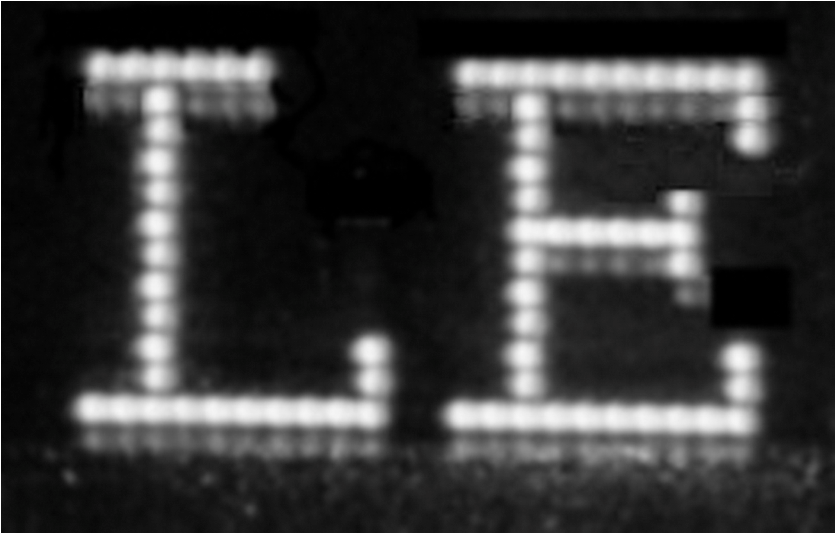
As is seen from the table, the crosstalk in the proposed 3-D system with active refraction is equal to the crosstalk in the FPR-type stereoscopic TV. In the aforementioned experiments, the dynamic crosstalk was rather low (0.9%) even at a high frame rate, 120 Hz, because of special measures applied to the LCD panel and drive circuits. To see the effect of dynamic crosstalk we applied the same eyeglasses technique with an ordinary FPR display, operating at a frame frequency of 60 Hz. Figure 10 shows a magnified image of white letters on a black background. As seen in the aforementioned photo, the finest horizontal lines are doubled with a weaker ghost image. This effect can be clearly seen only on the magnified image or from a very short distance. At a viewing distance larger than 1 m, ghosting is not seen and horizontal lines of the letters are perceived as being as thin as the vertical lines up to a crosstalk level of about 40%. In conventional time-sequential stereoscopic TVs with SG, incorrect synchronization of shutters can cause a so-called pseudoscopic image with confused left and right perspectives. A similar effect can be expected in a system with retardation-switching glasses, described previously.4,5 In our 3-D TV system with active displacement glasses, correct stereoscopic effect persists even if the synchronization is incorrect. However, the finest details of the image can be displayed incorrectly that can be perceived as reduction of vertical resolution. For example, the fine curved line, shown in Fig. 11(a), appears as shown in Fig. 11(b) if the synchronization of the active glasses is incorrect. 6.ConclusionIn this paper, we first proposed and tested a new type of flicker-free active glasses with switchable refraction and full-resolution stereoscopic TV, based on these glasses. Full image resolution in the proposed TV system is achieved within two sequential subframes due to time sequential operation with a frame frequency of 120 Hz. The method of displaying images differs from a conventional interlaced mode in which the even displayed lines and the odd displayed lines are biased at one line pitch. The developed TV generates sequential subframes in which odd and even lines of the image are displayed sequentially by the same rows of the display without biasing. Only on the retina of the viewer’s eye does the picture appear as an interlaced image due to synchronous vibration of the eye’s visual axis by the active displacement glasses. Stereoscopic crosstalk in our new 3-D TV system does not exceed a rather low level, inherent in FPR TV (measured as 0.6%). The proposed glasses are based on periodically switchable beam displacement in a birefringent crystal. The prototypes of the glasses have been fabricated using a comparatively expensive process and materials. To be recommended for use in consumer 3-D TVs the manufacturing cost of the active glasses should be reduced. It is believed that the desired cost reduction can be achieved by using a polymerized liquid-crystal as a birefringent material. ReferencesD.-S. Kim et al.,
“New 240 Hz driving method for full HD quality 3D LCD TV,”
SID 10 Symp. Dig. Tech. Pap., 41
(1), 762
–765
(2010). http://dx.doi.org/10.1889/1.3500583 0097-966X Google Scholar
H. Hang et al.,
“A novel polarizer glasses-type 3D displays with a patterned retarder,”
SID 10 Symp. Dig. Tech. Pap., 41
(1), 1
–4
(2010). http://dx.doi.org/10.1889/1.3500405 0097-966X Google Scholar
D.-S. Kim and S. Shestak,
“Flicker-free shutter-glasses for full high-definition 3D viewing,”
SPIE Newsroom. Illumination and Display,
(2013). http://dx.doi.org/10.1117/2.1201306.004810 Google Scholar
Y. Tamura et al.,
“Full HD 3D Display using stripe-patterned retarder array and retardation-switching glasses,”
SID 10 Symp. Dig. Tech. Pap., 41
(1), 874
–877
(2010). http://dx.doi.org/10.1889/1.3500617 0097-966X Google Scholar
Y.-Y. Yeh and L. D. Silverstein,
“Limits of fusion and depth judgment in stereoscopic color displays,”
Hum. Factors, 32
(1), 45
–60
(1990). http://dx.doi.org/10.1177/001872089003200104 HUFAA6 0018-7208 Google Scholar
Y. Cheng,
“WDM technologies: passive optical components, part 1,”
Circulator, 84 Academic Press, San Diego
(2003). Google Scholar
J. Harrold, D. Wilkes and G. J. Woodgate,
“Switchable 2D/3D display—solid phase liquid crystal microlens array,”
in Proc. IDW,
1495
–1496
(2004). Google Scholar
S. Shestak and D.-S. Kim,
“How much crosstalk can be allowed in a stereoscopic system at different grey levels?,”
Proc. SPIE, 8288 829910
–828819
(2012). http://dx.doi.org/10.1117/12.910558 PSISDG 0277-786X Google Scholar
BiographySergey Shestak graduated from Moscow State University in 1972 and received his PhD degree in radio-physics in 1983. He worked for the Research and Development Institute of Radio-Optics (1972–1998) and the Institute of Optical Neural Technologies (1999–2003) in Moscow as a research scientist and a head of the laboratory, and the Korea Institute of Science and Technology in Seoul (1993–2001) as a visiting researcher. Currently, he is with Samsung Electronics. His fields of interest includes display optics and holographic and 3-D display techniques. Dae-Sik Kim received his PhD degree from Osaka University, Osaka, Japan, in 1998. From 1998 to 1999, he was a researcher of the Venture Business Laboratory at Osaka University, Japan. In 1999, he joined the Digital Media Communication R&D Center, Samsung Electronics, Republic of Korea. His R&D interests include 3-D and holographic display, next-generation display systems, and their applications. Kyung-Hoon Cha received his MS degree from Kyunghee University, Gyeonggi, Republic of Korea, in 2000. From 1998 to 2000, he was a researcher in the Optical Communication Laboratory at Kyunghee University. In 2000, he joined the Digital Media Communication R&D Center, Samsung Electronics, Republic of Korea. His R&D interests include 3-D and holographic display, reflective display systems, and their applications. |