
|
|
1.IntroductionTo facilitate the applications of object-oriented storage, retrieval, editing, and interaction, modern multimedia communications require that video content has to be easily accessible on an object basis. The MPEG-4 video compression standard provides such functionalities by describing video objects not only by texture but also by shape. Because of severe mobile environments and massive image and video retrieval demands, a good shape coding scheme has to provide an efficient compression as well as effective description.1 These two requirements have been extensively investigated in data compression2–4 and pattern recognition fields5–7 separately in two recent decades. However, jointly considering both objectives in one framework remains an open problem. It is well known that the vertex-based shape representation can handle both shape coding and shape description in a natural way. As a result, this representation can be directly applied to the contour-based object-oriented applications. In general, there are two main vertex-based shape coding frameworks. One is the iterative refinement framework.2–4 It treats the vertex selection and encoding separately; therefore, it loses the rate-distortion (RD) optimality. The other is the operational rate-distortion (ORD) optimal framework.1,8,9 It jointly considers the vertex selection and encoding as a shortest path problem in a directed acyclic graph (DAG); therefore, it can guarantee the optimality in the RD sense. The main limitation of the ORD optimal framework, however, is that the optimality is contingent on the chosen parameters. Thus, the performance enhancements to this framework are to relax the constraints of these parameters. Many relaxations used in the ORD optimal framework have been focused on the admissible vertex set,1,9,10 the sliding window strategy,1,10,11 the edge distortion measurement,1,12–16 and the code table,17–19 but few have been concentrated on the edge encoding structure. Their problem to be addressed is to find an optimal polygon that can be encoded with the lowest bit rate for a given admissible distortion, where the optimality is contingent on the given eight-direction edge encoding structure.20 Since the location of the current vertex is strongly correlated with the location of the previous one, it is often assumed that the vertices are encoded differentially. Thus, the bit rate for the entire polygon is the sum of all the edge rates that are determined not only by the code table but also by the edge encoding structure. Besides, the approximation quality depends largely on the ability of edge encoding structure to represent the contour characteristics. Therefore, the edge encoding structure plays a vital role in both compression and description performances. There is an inherent limitation in the eight-direction structure. The edge available for this structure should be restricted to intersect the horizontal axis in an angle which is an integer multiple of (named as restricted edge). The edge that is not in one of these eight restricted directions (named as unrestricted edge) cannot be selected, despite that the edge distortion is no larger than the given admissible distortion. Consequently, it results in the following two problems, as shown in Figs. 1(a) and 1(b):
Fig. 1Comparison results for the Neck region of the 31st frame of the MissAmerica.qicf sequence with . Here, we select the upper left corners as the first vertices and use the run length codes to encode the edge. (a) Eight-direction structure with , ; (b) zoom-in on the portions highlighted by the rectangle in (a); (c) eight-sector structure with , ; (d) 16-sector structure with , . As we can see, eight-direction structure produces a host of redundant short edges, so it is a waste of bits; our two arbitrary direction structures can avoid these redundant short edges, so they save a large number of bits as well as produce more compact results (Notations—: admissible distortion; VN: vertex number; : encoding bits; Legends—dashed line: original contour; solid line: approximated polygon; asterisk: vertex). 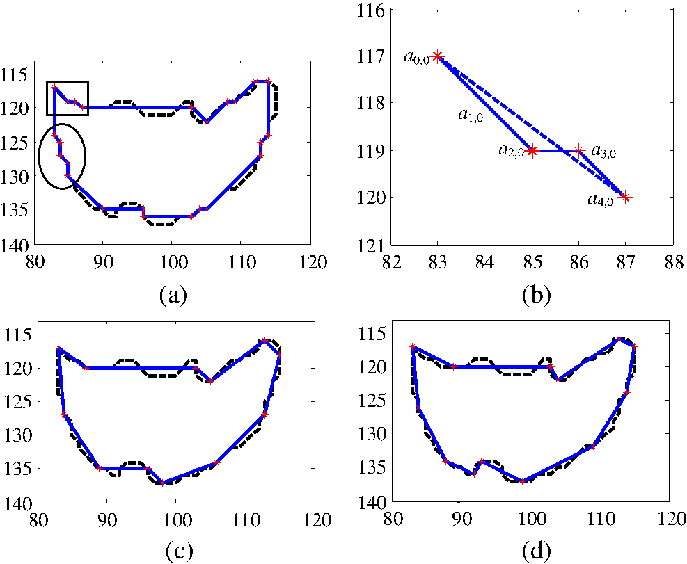 The above phenomena motivate us to relax the edge direction restriction. To achieve this, we propose two arbitrary direction edge encoding structures, called the 8- and the 16-sector structures, which can encode both the restricted and unrestricted edges. First, we partition the digital coordinates into 8 or 16 sectors, and then decompose the encoding edge into a short component and a long component. After that, we encode the sector information with a fixed length code (FLC), the short and the long components with either the run length codes (RLC) or the variable length codes (VLC) in a different way, providing a further encoding bit reduction. We seamlessly embed these structures into the ORD optimal vertex-based shape coding algorithms with various parameter setups to improve their RD performance as well as to achieve better description results. Some representative results produced by our proposals are shown in Figs. 1(c) and 1(d). The rest of this paper is organized as follows. Section 2 introduces the ORD optimal shape coding framework, the related enhancements, and the traditional eight-direction edge encoding structure. Section 3 presents the 8- and the 16-sector edge encoding structures, respectively. Full analyses of the experimental results on both shape coding and hand gesture recognition are provided in Sec. 4. Finally, conclusions and future work are given in Sec. 5. 2.Related Work2.1.Operational Rate-Distortion Optimal Shape CodingLet the ordered set denote the connected contour, where is the ’th pixel of , is the total number of pixels in , and for a closed contour. Let the ordered set denote the admissible vertex set, where , is the ’th admissible vertex associated with , and is the number of admissible vertices in associated to . Let denote the length of the sliding window in pixel along the contour, starting at contour point . Let the two-tuple set denote the candidate edges for polygonal approximation. Let the ordered set denote the polygon used to approximate , where is the ’th vertex of , is the total number of vertices in , and . Let denote the bit rate of the edge and the bit rate for the entire polygon. Let denote the distortion of the edge , the polygon distortion, and the admissible distortion. The ORD shape coding finds an optimal polygon in the admissible vertex set which can be encoded with the lowest bit rate for a given admissible distortion .8 It can be formulated as follows: where is the sum of all the edge rates and is the maximum edge distortion.Formulation (1) is virtually a shortest path problem in a weighted DAG , as shown in Fig. 2.9 A valid path of order from vertex to a vertex is an ordered set is an ordered set , such that for , whose length is defined as follows: where is a weight function of the edge defined as follows:Fig. 2Modeled DAG and the shortest path of Fig. 1(d) (Notation—arrow: candidate edge with weights given by the eight-direction/eight-sector structure). 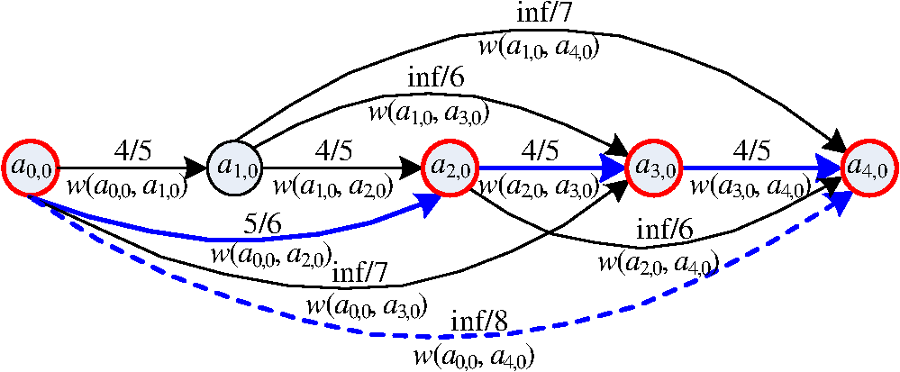 The above definition of the weight function leads to the length of infinity for every path, which includes an edge with the distortion above . Therefore, the shortest path will not include this edge. Every finite-length path that starts at vertex and ends at vertex results in a path length equal to the rate of the polygon it represents. Therefore, the shortest of all these paths corresponds to the polygon with the smallest bit rate, which is the solution to the problem in (1). Let represents the minimum rate from to via a polygon approximation. Let be the back pointer of , which is used to remember the optimal path. Then, the solution of the shortest path can be found efficiently by the DAG shortest path algorithm21 formalized in Algorithm 1. Algorithm 1The ORD optimal shape coding algorithm.
We will explain how Algorithm 1 works. In lines 1 and 2, the admissible vertex set and the length of the sliding window length for each contour point are calculated. In line 3, the rate for encoding the starting point of the contour is assigned to the rate of the first polygon vertex, and the rate for reaching any of the admissible vertex is set to infinity. The “for loops” in lines 4 and 5 select the start vertex of a polygon edge and the “for loops” in lines 6 and 7 select its end vertex within the sliding window of the start vertex. The lines 8–10 are used to calculate the edge distortion and the edge rate, by which the edge weight can be determined. The most important part of this algorithm is the comparison in line 11. Here, it tests whether the new minimum rate, , to reach admissible vertex , given that the last vertex was , is smaller than the smallest minimum rate used so far to reach , . If this minimum rate is indeed smaller, then it is assigned as the new smallest minimum rate to reach admissible vertex , , and the back pointer of , is assigned to point to since this is the previous vertex used to achieve . This algorithm leads to the optimal solution because when the rate of a vertex is given, then the selection of the future vertices , is independent of the selection of the past vertices , . 2.2.Enhancements to the Operational Rate-Distortion Optimal Shape CodingAs we can see, the major problem in the ORD optimal shape coding algorithm is that the optimality is contingent on the chosen admissible vertex set,1,9,10 sliding window strategy,1,10,11 distortion measurement,12–16 code table,17–19 and the edge encoding structure. The former four parameters have been intensively investigated to relax their constraints and improve the shape coding performance. Here, we provide a brief summary.
2.3.Traditional Eight-Direction Edge Encoding StructureWhile intensive investigations have been made on the above four parameters, little attention has been paid to the edge encoding structure. Almost all the vertex-based ORD optimal shape coding algorithms employ the eight-direction edge encoding structure.20 In this structure, the eight-connected chain code and the run-length encoding are combined by representing the edge between two admissible vertices by an angle and a run , which form the symbol , as illustrated in Fig. 3(a). Each of the possible symbols gets a probability assigned and the resulting stream of the polygon ’s edges can be optimally encoded using these probabilities. Fig. 3Illustration of (a) the angle and the run of the eight-direction structure, (b) the quadrant number, the -component magnitude, and the -component magnitude of the quadrant structure, (c) the sector number, the short component magnitude, and the long component magnitude of the eight-sector structure, and (d) the sector number, the short component magnitude, and the long component magnitude of the 16-sector structure (Legend—solid line: encoding edge; asterisk: vertex; long dashed line: edge component; dashed line in (a): admissible positions for the next vertex given the current vertex at the origin; dashed line in (b): quadrant boundary; dashed line in (c) and (d): sector boundary).  In practical implementations, the design of code is under the hypothesis that the probability mass function of is separable20 and is uniformly distributed over all the eight restricted directions. Thus, can be encoded separately and the optimal code for is a 3-bit FLC. There are two main codes for . One is based on the hypothesis that is geometrically distributed with a parameter . In this case, the optimal code for is a RLC with zeros and a final “1.” Note that any positive integer value of is codable; therefore, the code has no edge length restriction. The other is based on the hypothesis that is piecewise uniformly distributed. In this case, the optimal code for is a VLC, which has the general form , where is the length of . Note that the largest possible value of has to be a finite positive integer . A smaller often results in fewer bits for each edge, but requires more edges for the entire polygon. Conversely, a larger often results in fewer edges, but requires more bits for each edge. Usually, makes a good balance between the edge rate and the edge number over a wide range of contour characteristics and admissible distortions.11 Thus, 15 codewords are needed. Reference 20 gives a typical example of such code table that and are a 2-bit FLC and a -bit FLC, respectively, where is the floor operator. To illustrate the eight-direction structure-based edge encoding scheme for encoding an edge, consider a restricted edge (for simplicity, we use the coordinates of the ending point as the coordinates of the edge when this edge starts at the origin, similarly hereinafter), as shown in Fig. 3(a). Its angle and run take the values of and 7, which are encoded with a 3-bit FLC and a 7-bit RLC (a 4-bit VLC), resulting in 10 bits (7 bits) in total. The above eight-direction structure-based edge encoding scheme is quite simple and easy to implement. However, the inherent limitation can be clarified as follows. From a structural perspective, the uniquely decodable code for each edge consists of two parts representing and , and the total length of this code is when RLC is used or when VLC is used. For simplicity, assume that an edge of run approximates a contour segment of pixels. Then, the efficiency of this code, usually measured by the bits per contour pixel, is () or (). Note that both sequences are increasing as decreases; therefore, the shorter the run, the less efficient these codes are. Figures 1(a) and 1(b) show that many short restricted edges are needed for the contour segments which are not exactly in eight restricted directions. Therefore, the eight-direction edge encoding structure is inefficient. From a description perspective, a good shape description should make the proportion of selected vertices at or near the corners of the original shape contour as high as possible so as to benefit the object-oriented applications.22 However, when the contour segments are not exactly in eight restricted directions, the eight-direction structure not only consumes a large number of closely spaced vertices, but also strengthens the contour quantization error and noise disturbances. This affects the subjective experiences of reconstruction contours as well as degrades the performance of the object-oriented applications. Further, to reveal the problem of the existing eight-direction structure quantitatively from a systematic perspective, we map the contour segment in Fig. 1(b) into a weighted DAG, as shown in Fig. 2. It is observed that all 10 edge distortions uphold the admissible distortion, but 5 out of 10 edge weights are assigned infinity due to the direction restriction, making the shortest path in DAG quite long and thus the bit rate for the entire polygon much larger. Therefore, we should relax the direction restriction to increase the number of available edges. The following section follows this idea. 3.Arbitrary Direction Edge Encoding Structures3.1.Eight-Sector Edge Encoding StructureA simple and intuitive structure for an edge of arbitrary direction consists of a quadrant number , an -component magnitude , and an -component magnitude , which form the symbol . The quadrant number is defined as: quadrant 0 is the set of such that , , quadrant 1: , and quadrant 3: , , as illustrated in Fig. 3(b). Assume that , , and are independently distributed; is uniformly distributed over all the four quadrants; and are geometrically or piecewise uniformly distributed. Then, can be separately and optimally encoded with a 2-bit FLC and and can be optimally encoded with RLCs or VLCs. The procedures to implement the quadrant structure-based edge encoding scheme are as follows:
Now we compare the performance of this quadrant structure with the traditional eight-direction one. If RLC is selected, for the quadrant structure, the bit rate for the symbol , denoted by , is while for the eight-direction structure, we have for the restricted edge, thus the bit rate for the symbol , denoted by , isCompared Eq. (4) with Eq. (5), we have when . Thus, although the quadrant structure can change the unrestricted edge rate from infinity to a finite value, it increases the diagonal direction edge rate from to , resulting in bits increment. Assume that an edge of run approximates a contour segment of pixels. Then, for the the diagonal direction edge, the quadrant structure changes the code efficiency from to , resulting in 1 bit increment per contour pixel. Such a large cost makes the quadrant structure unfeasible in practice. With a similar comparison method, we can draw the same conclusion for the VLC case. To illustrate this deficiency in the quadrant structure-based edge encoding scheme, reconsider the restricted edge , as shown in Fig. 3(b). Its quadrant numbers, -component magnitude and -component magnitude, take the values of 2, 7, and 7, which are encoded with a 2-bit FLC, an 8-bit RLC (a 5-bit VLC), and a 7-bit RLC (a 4-bit VLC), resulting in 17 bits (11 bits) in total. This is 7 bits (4 bits) more than those used by eight-direction structure. The reason that the quadrant structure does not work well is that there exists dependency between the - and the -component magnitudes and the independency assumption is unreasonable. It motivates us to make a good use of this dependency. To achieve this aim, we design an edge encoding structure consisting of a sector number , a short component magnitude , and a long component magnitude , which form the symbol . From Ref. 2, we define the sector number as: sector 0 is the set of such that , sector 1: , and sector 7: , as illustrated in Fig. 3(c). The short component is the smaller component of the edge’s - and -components, while the long component is the larger component of them. Because the long component magnitude is not smaller than the short component magnitude , we can encode with differential encoding method. In this way, we can make a good use of the dependency between the - and the -component magnitudes, and allow a further reduction in the number of bits used. Let denote the difference between and , i.e., . In our practical implementation, we design the code under the the hypothesis that the probability mass function of is separable and is uniformly distributed over all the eight sectors. Thus, can be separately and optimally encoded with a 3-bit FLC. Similarly with the assumption about the run in the eight-direction structure-based scheme,20 we simply assume that both and are geometrically or piecewise uniformly distributed. Therefore, the optimal codes for both and are RLCs or VLCs. The procedures to implement the eight-sector structure-based edge encoding scheme are as follows:
If VLC is selected, similarly with the run encoding in the eight-direction structure-based scheme, the magnitudes of both - and - components are restricted to a predefined number . Thus, we should design a series of code tables of the ranges from 1 to 1, 1 to 2, 1 to for both and . A series of reference code tables with are shown in Table 1. Then, encode according to the table of the range from 1 to and encode according to the table of the range from 1 to . Table 1Variable length encoding table for ε=15. The number of bits is determined by both the range and the value of β8-sec (β16-sec) or δ8-sec (δ16-sec).
Here, we reason why this structure works better than the traditional eight-direction one. If RLC is selected, for the eight-sector structure, the bit rate for the symbol , denoted by , is where when the encoding edge is in the restricted direction. Comparing Eq. (6) with Eq. (5), we can see that although the eight-sector structure increases the restricted edge rate by 1 bit, it can change the unrestricted edge rate from infinity to an acceptable finite value. Therefore, a large number of bits can be saved in average. With similar comparison method, we can draw the same conclusion for the VLC case.3.2.Sixteen-Sector Edge Encoding StructureThe above eight-sector structure defines the short component magnitude and the long component magnitude as the smaller and the larger magnitudes of the edge’s - and -components, and encode and the difference in a separate way. If RLC is selected, this structure requires bits. Although it can basically keep the bit rate for restricted edges, it will lead to a relatively larger number of bits for unrestricted edges, especially when both and take large values. The reason for this inefficiency is that there exists dependency between and and the independency assumption is unreasonable. It motivates us to make a good use of this dependency. To achieve this aim, we design an edge encoding structure consisting of a sector number , a short component magnitude , and a long component magnitude , which form a symbol . The sector number is defined as: sector 0 is the set of such that , sector 1: , and sector 15: , as illustrated in Fig. 3(d). The short component is the smaller component of the edge’s two octant direction components with difference in angle, while the long component is the larger component of them. Because the long component magnitude is not smaller than the short component magnitude , we can encode with differential encoding method. Compared Fig. 3(d) with Fig. 3(c), we have and . Therefore, in this way, we can make a good use of the dependency between the short and the long component magnitudes of the eight-sector structure, and allow a further reduction in the number of bits used. In our practical implementation, we use the same hypotheses and the corresponding optimal codes as we used in the eight-sector structure. The procedures to implement the 16-sector structure-based edge encoding scheme are as follows:
If VLC is selected, the magnitudes of both - and -components are restricted to . Thus, we should design a series of code tables of the ranges from 1 to 1, 1 to 2, …, 1 to for both and . Table 1 can also be used here:
Here, we reason why this structure with RLC can outperform the eight-sector one from a data compression perspective. For the 16-sector structure, the bit rate for the symbol , denoted by , is where and . Compared Eq. (7) with Eq. (6), we can see that although the 16-sector structure increases the restricted edge rate by 1 bit, it can change the unrestricted edge rate from to , resulting in the bits decrement. Assume that the edge direction is uniformly distributed, then from Fig. 3(d), we can see that the probability that will occur is far more than the probability that will occur. Therefore, a large number of bits can be saved in average.To illustrate this advantage, consider an unrestricted edge , as shown in Figs. 3(c) and 3(d). For the eight-sector structure, its sector number, short component magnitude, and long component magnitude take the values of 2, 3, and 7, which are encoded with a 3-bit FLC, a 4-bit RLC (4-bit VLC), and a 4-bit RLC (4-bit VLC), resulting in 11 bits in total. For the 16-sector structure, they take the values of 4, 3, and 4, which are encoded with a 4-bit FLC, a 4-bit RLC (a 3-bit VLC), and a 1-bit RLC (a 2-bit VLC), resulting in 9 bits in total. Thus, two bits are saved. However, this bit reduction will degrade the ability in contour description. To look deep into this phenomenon, we plot the isorate contours for both the eight- and the 16-sector structures on Fig. 4, i.e., the traces of the ending points of the encoding edges having the same starting point and rate. For simplicity, assume that an edge of long component magnitude approximates a contour segment of pixels. We can see that for the eight-sector structure, the edges of the same rate have the same , thus can approximate contour segments of the same length in pixel. Therefore, for the eight-sector structure, the codes for the edges of the same rate have the same efficiency in terms of the bits per contour pixel. Instead, for the 16-sector structure, the edges of the same rate have different . To be more specific, the edges of directions () have the maximum length over all the directions (named as preferential direction), while the edges of the restricted directions have the minimum length (named as nonpreferential direction), as shown in Fig. 4(b). Thus, the edges of the same rate but of different directions will approximate contour segments of the different lengths in pixel. Therefore, for the 16-sector structure, the codes for the edges of the same rate have different efficiencies, i.e., the codes for edges in or near the preferential directions have relatively higher efficiencies, whereas the codes for the edges in or near the nonpreferential directions have relatively lower efficiencies. This may bias the edge selection toward preferential directions via the ORD optimal framework, thereby giving false corners when contour segments are in or near the nonpreferential directions. We call it direction bias effect. Fig. 4(a) Isorate contour of the eight-sector structure when , (b) isorate contour of the 16-sector structure when , where the direction bias effect happens when contour segments are in or near the nonpreferential directions (Legend—solid line: isorate contour; dashed line in (a): restricted direction; long dashed line in (b): preferential direction; dashed line in (b): nonpreferential direction; dotted line in (b): encoding edge for the 8-sector structure; dashed dotted line in (b): encoding edge for the 16-sector structure; asterisk in (b): vertex).  To illustrate this effect, we take the approximation of the horizontal contour segment from point to point shown in Fig. 4(b) as an example. For the eight-sector structure, among all approximations, the one directly using edge is of the most efficiency. However, for the 16-sector structure, according to Eq. (7), nonpreferential direction edge will consume 17 bits, whereas two preferential direction edges and consume 8 bits and 8 bits, respectively, resulting in 16 bits in total. Thus, the ORD optimal framework may select these two edges rather than edge to approximate the horizontal contour segment, which gives a false corner . This effect may significantly affect the performance of related object-oriented applications, which will be further displayed in the next section. 4.Experimental ResultsTo analyze the performance of the ORD optimal framework with our two arbitrary direction edge encoding structures in both data compression and pattern recognition fields, various ORD optimal shape coding algorithms with different parameter configurations are applied to both shape coding and hand gesture recognition. The ADMSC is chosen for contour distortion measurement.16 To clarify the nomenclature adopted, the following three-parameter notation is used: Admissible vertex band type, Edge encoding structure type, and Code table type. Admissible vertex band (AVB) type refers to whether the AVB of width 1 pel is used; Edge encoding structure type refers to the choice of 8-direction, 8-sector, and 16-sector structure; and Code table type refers to the choice of RLC and VLC (the default type is RLC). Therefore, for instance, Basic-8-Direction-RLC means that the algorithm is based on the eight-direction structure with RLC where the AVB technique is not used. 4.1.Arbitrary Direction Edge Encoding Structures for Shape CodingFor the RD performance assessments, five MPEG-4 binary shape sequences, namely Weather.qcif, News.qcif, Stefan.sif, Children.sif, and Forman.cif, are used. These sequences have various spatial and temporal resolutions. Figure 5(a) shows the cumulative RD curves generated with different ORD optimal algorithms. As expected, our two structures always outperform the traditional eight-direction structure, with up to 48.9% bit savings. Figure 5(b) compares the number of available edges between eight-direction and our arbitrary direction structures on Stefan sequence when . The numbers of edges available for our arbitrary direction structures without AVB and with AVB are 3–6.3 and 3.5–5.5 times of those available for the eight-direction structure. These additional available edges provide the ORD optimal framework more opportunities to find a shorter shortest paths in a weighted DAG with much less infinity weights. That is why our structures can result in much fewer encoding bits than the eight-direction one, which is consistent with the analysis given in Sec. 2.3. It also indicates how important the direction relaxation is from a compression perspective. Fig. 5Compression performance comparisons. (a) Cumulative RD results from five sequences calculated by various ORD optimal algorithms; (b) number of available edges calculated frame by frame on the Stefan sequence when . 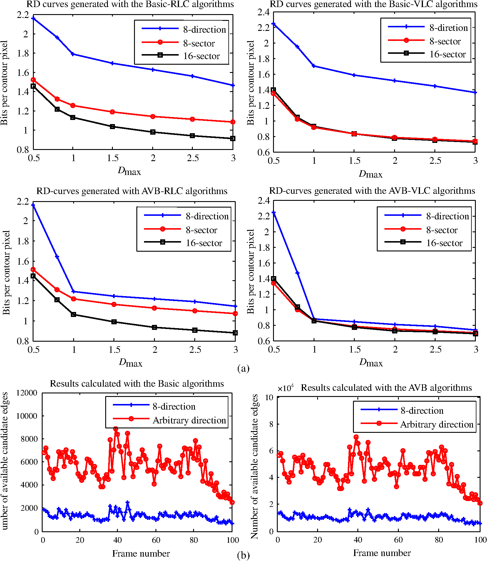 Figure 5(a) also reveals that the coding gain varies with different parameter configurations. Here, we only point out the variations with two different configurations and give explanations as follows.
For the description assessments, the Stefan object of the 100th frame of the Stefan sequence has been used. Figure 6 shows the polygons generated with various ORD optimal algorithms. Considering the first column as an example, we can see that the traditional eight-direction structure needs 68 vertices for contour approximation, but both of our structures only need 28 vertices. As a result, the traditional one needs 453 bits, whereas our two proposals need 359 and 325 bits for contour encoding, resulting in 94 and 128 bit savings, respectively. Fig. 6Description ability comparisons among various ORD optimal algorithms on the Stefan object (Legends—solid line: approximating polygon; dashed line: original contour; asterisk: vertex). (a) Traditional eight-direction edge encoding structure, (b) proposed eight-sector edge encoding structure, (c) proposed 16-sector edge encoding structure.  Moreover, we see that the polygons approximated by our proposals are quite compact and have strong ability to reflect the characteristics of the original object contour, since a relatively straight contour segment is easier to be approximated by an edge, so that the turns of the polygons are more likely to be the corners of the object contour. This will benefit the successive object-oriented applications. In the next section, we will apply these polygons to hand gesture recognition. 4.2.Arbitrary Direction Edge Encoding Structures for Hand Gesture RecognitionHand gesture recognition is of great importance in human-computer interaction. Usually, the shape feature is sufficient for successful recognition.23 However, due to the nature of optical camera, the quality of captured images is sensitive to the lighting conditions and cluttered backgrounds, which makes it very difficult to obtain hand shapes.24 Due to the new advent of Kinect depth camera (Shenzhen, China),25 new opportunities for shape-based hand gesture recognition emerge. With the Kinect depth camera, we collect three hand gesture categories, namely Rock, Paper, and Scissors; each category has 50 samples, which contain various rotations, scales, viewpoints, and even self-occlusions. Then, by thresholding from the nearest depth position with a certain gap, we can obtain the hand shapes robustly. Some exemplars, including their color maps, depth maps, and segmented hand shapes, are illustrated in Fig. 7. Fig. 7Illustration of our hand gesture dataset captured by the Kinect camera. The first and second columns are the color and depth maps in our dataset, and the third column is the segmentations of hands. 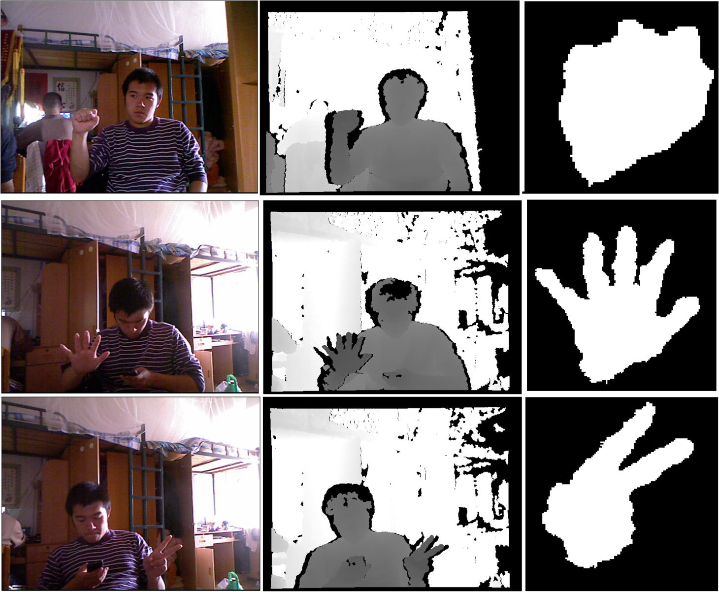 However, even with the help of Kinect camera, due to the limited camera resolution and the complex monitoring environment, quantization error and contour noise are almost inevitable in shape acquisition. Since the ORD optimal algorithms with our two arbitrary edge encoding structures can approximate the contour segments with arbitrary directions, quantization error, and contour noise, it is suitable to handle this recognition task. Here, we only choose RLC to guarantee that there is no limitation on the encoding edge length. We approximate the hand shape contour by the polygons using our proposals. It is important to determine a proper . We let be proportional to the radius of the maximal inscribed disk of the hand shape, so that is adaptive to the size of palm. To be specific, we set to 30% of the radius, as this can well discriminate nonsalient fingers from large shape deformations. Only the negative turns of the polygons are considered, since it was reported that the negative corners are much more informative than the positive ones.26 Suppose that there are negative turns, we classify a hand gesture to Rock if , Paper if , and Scissors otherwise. Table 2 provides the confusion matrices and the mean recognition accuracies for various ORD optimal algorithms with our two arbitrary direction structures. As expected, the mean accuracies of the eight-sector structure are much higher than those of the 16-sector structure due to the direction bias effect as mentioned in Sec. 3.2. Table 2Confusion matrices for Basic-8-Sector/Basic-16-Sector and AVB-8-Sector/AVB-16-Sector algorithms. The mean recognition accuracies are 93.33%/86% and 94%/76%, respectively. For each gesture category, the higher recognition accuracy between the 8-sector structure and the 16-sector structure is marked in bold. We can see that 8-sector structure always results in higher recognition accuracy, endorsing the earlier comment about 8-sector structure having stronger description ability than 16-sector one.
To further reveal this direction bias effect, Fig. 8 shows some results selected from our collected dataset. The odd columns show the hand gestures correctly recognized by both of our structures, while the even columns show those correctly recognized by the eight-sector structure but wrongly recognized by the 16-sector structure, except the Paper results which are wrongly recognized by the Basic-16-Sector algorithms. We take the second Rock gesture recognized by the Basic algorithms as an example. Although the 16-sector structure can reduce the total rates from 259 to 202 bits compared with the eight-sector structure, the bottom right contour segment of the direction near the restricted direction of zero is approximated by two edges of the directions near the preferential directions of due to the direction bias effect, and therefore, a false-negative turn is generated. It demonstrates that the 16-sector structure does well in compression but is not good at description for object-oriented applications, which is the opposite of the eight-sector structure. Fig. 8Hand gesture recognition by the negative turn detection (Legends—solid line: approximating polygon; dashed line: original contour; asterisk: vertex; dot: negative turn). (a) Contour approximations of the Rock gestures, (b) contour approximations of the Paper gestures, (c) contour approximations of the Scissors gestures. 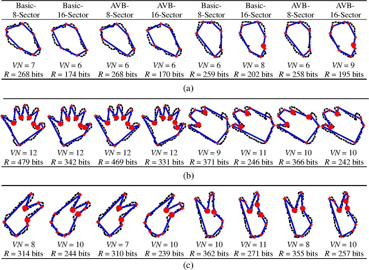 5.Conclusions and Future WorkIn this paper, we have presented two edge encoding structures, namely 8- and 16-sector structures, for the ORD optimal framework, to relax the direction restriction of the traditional eight-direction structure. Both consist of the sector number, the short component magnitude, and the long component magnitude, which are encoded with the optimal code words under two probability distribution assumptions. Although these two structures are quite simple, experiments on both shape coding and hand gesture recognition validate that the ORD optimal framework with our proposals can achieve high coding gains and mean recognition rates, which makes our proposals potentially promising in the applications of both data compression and pattern recognition fileds. Several research directions based on our proposals are possible. RLC has no limitation on the encoding edge length but is of low efficiency; thus, it is applicable to the object-oriented applications but not to the storage and transmission, whereas VLC exactly opposes it. How to combine their advantages and avoid disadvantages is one research direction, with some preliminary results shown in Ref. 27. Moreover, although our arbitrary direction structures avoid redundant short edges, they still cause noticeable edge errors. How to reduce them, so that the approximate polygon can be applicable to the more challenging shape-based depth map coding28,29 and shape-based vision tasks,30,31 is another research direction, with some preliminary results shown in Ref. 32. AcknowledgmentsThe authors would like to thank Hans Georg Musmanna, Michael Höttera, and Jörn Ostermanna for providing the MPEG-4 binary shape sequences on the Internet, and Shaojun Zhu for collecting the hand gestures with a Kinect camera. The authors wish to thank Baolan Yan, Zhe Wang, and Zhou Ren for providing their source codes. The authors also want to thank Junsong Yuan, Wenyu Liu, and Chun Wang for their discussions, and two anonymous reviewers for their suggestions. This work was supported in part by the National Natural Science Foundations of China (Grant Nos. 61303238 and 61202460), the Hubei Provincial Natural Science Foundation of China (Grant No. 2013CFB214), the Wuhan Municipal Key Technologies Research and Development Programs (Grant Nos. 2013011001010484, 2013011001010463, and 201250499145-24), and the Wuhan Innovative Talent Development Fund to Dr. Tonghui Qian. ReferencesA. K. Katsaggeloset al.,
“MPEG-4 and rate-distortion-based shape-coding techniques,”
Proc. IEEE, 86
(6), 1126
–1154
(1998). http://dx.doi.org/10.1109/5.687833 IEEPAD 0018-9219 Google Scholar
K. J. O’Connell,
“Object-adaptive vertex-based shape coding method,”
IEEE Trans. Circuits Syst. Video Technol., 7
(1), 252
–255
(1997). http://dx.doi.org/10.1109/76.554440 ITCTEM 1051-8215 Google Scholar
J. Chunget al.,
“A new vertex-based binary shape coder for coding efficiency,”
Signal Process.: Image Commun., 15
(7–8), 665
–684
(2000). http://dx.doi.org/10.1016/S0923-5965(99)00046-6 SPICEF 0923-5965 Google Scholar
C.-M. KuoC.-H. HsiehY.-R. Huang,
“A new adaptive vertex-based binary shape coding technique,”
Image Vis. Comput., 25
(6), 863
–872
(2007). http://dx.doi.org/10.1016/j.imavis.2006.06.004 IVCODK 0262-8856 Google Scholar
T. AdamekN. E. O’Connor,
“A multiscale representation method for nonrigid shapes with a single closed contour,”
IEEE Trans. Circuits Syst. Video Technol., 14
(5), 742
–753
(2004). http://dx.doi.org/10.1109/TCSVT.2004.826776 ITCTEM 1051-8215 Google Scholar
E. AttallaP. Siy,
“Robust shape similarity retrieval based on contour segmentation polygonal multiresolution and elastic matching,”
Pattern Recogn., 38
(12), 2229
–2241
(2005). http://dx.doi.org/10.1016/j.patcog.2005.02.009 PTNRA8 0031-3203 Google Scholar
C. XuJ. LiuX. Tang,
“2D shape matching by contour flexibility,”
IEEE Trans. Pattern Anal. Mach. Intell., 31
(1), 180
–186
(2009). http://dx.doi.org/10.1109/TPAMI.2008.199 ITPIDJ 0162-8828 Google Scholar
G. M. SchusterA. K. Katsaggelos,
“An optimal polygonal boundary encoding scheme in the rate distortion sense,”
IEEE Trans. Image Process., 7
(1), 13
–26
(1998). http://dx.doi.org/10.1109/83.650847 IIPRE4 1057-7149 Google Scholar
G. M. SchusterG. MelnikovA. K. Katsaggelos,
“Operationally optimal vertex-based shape coding,”
IEEE Signal Process. Mag., 15
(6), 91
–108
(1998). http://dx.doi.org/10.1109/79.733498 ISPRE6 1053-5888 Google Scholar
F. A. SohelL. S. DooleyG. C. Karmakar,
“New dynamic enhancements to the vertex-based rate-distortion optimal shape coding algorithm,”
IEEE Trans. Circuits Syst. Video Technol., 17
(10), 1408
–1413
(2007). http://dx.doi.org/10.1109/TCSVT.2007.903788 ITCTEM 1051-8215 Google Scholar
F. A. Sohelet al.,
“Sliding-window designs for vertex-based shape coding,”
IEEE Trans. Multimedia, 14
(3), 683
–692
(2012). http://dx.doi.org/10.1109/TMM.2011.2182507 ITMUF8 1520-9210 Google Scholar
L. P. KondiG. MelnikovA. K. Katsaggelos,
“Joint optimal object shape estimation and encoding,”
IEEE Trans. Circuits Syst. Video Technol., 14
(4), 528
–533
(2004). http://dx.doi.org/10.1109/TCSVT.2004.825569 ITCTEM 1051-8215 Google Scholar
F. A. SohelL. S. DooleyG. C. Karmakar,
“Accurate distortion measurement for generic shape coding,”
Pattern Recogn. Lett., 27
(2), 133
–142
(2006). http://dx.doi.org/10.1016/j.patrec.2005.07.006 PRLEDG 0167-8655 Google Scholar
F. A. SohelL. S. DooleyG. C. Karmakar,
“Fast distortion measurement using chord-length parameterization within the vertex-based rate-distortion optimal shape coding framework,”
IEEE Signal Process. Lett., 14
(2), 121
–124
(2007). http://dx.doi.org/10.1109/LSP.2006.882099 IESPEJ 1070-9908 Google Scholar
Z. Laiet al.,
“Perceptual distortion measure for polygon-based shape coding,”
IEICE Trans. Inf. Syst., E96.D
(3), 750
–753
(2013). http://dx.doi.org/10.1587/transinf.E96.D.750 ITISEF 0916-8532 Google Scholar
F. A. Sohelet al.,
“Geometric distortion measurement for shape coding: a contemporary review,”
ACM Comput. Surv., 43
(4), 1
–29
(2011). http://dx.doi.org/10.1145/1978802 ACSUEY 0360-0300 Google Scholar
G. MelnikovG. M. SchusterA. K. Katsaggelos,
“Simultaneous optimal boundary encoding and variable-length code selection,”
in Proc. IEEE Int. Conf. on Image Processing,
256
–260
(1998). Google Scholar
G. MelnikovG. M. SchusterA. K. Katsaggelos,
“Shape coding using temporal correlation and joint VLC optimization,”
IEEE Trans. Circuits Syst. Video Technol., 10
(5), 744
–754
(2000). http://dx.doi.org/10.1109/76.856451 ITCTEM 1051-8215 Google Scholar
G. MelnikovA. K. Katsaggelos,
“Shape approximation through recursive scalable layer generation,”
in Proc. IEEE Int. Conf. on Image Processing,
915
–918
(2000). Google Scholar
G. M. SchusterA. K. Katsaggelos, Rate-Distortion Based Video Compression: Optimal Video Frame Compression and Object Boundary Encoding, Kluwer, Norwell, MA
(1997). Google Scholar
T. CormenC. LeisersonR. Rivest, Introduction to Algorithms, McGraw-Hill, New York
(1991). Google Scholar
J. De WinterJ. Wagemans,
“The awakening of attneave’s sleeping cat: identification of everyday objects on the basis of straight-line versions of outlines,”
Perception, 37
(2), 245
–270
(2008). http://dx.doi.org/10.1068/p5429 PCTNBA 0301-0066 Google Scholar
J. P. Wachset al.,
“Vision-based hand-gesture applications,”
Commun. ACM, 54
(2), 60
–71
(2011). http://dx.doi.org/10.1145/1897816 CACMA2 0001-0782 Google Scholar
A. Erolet al.,
“Vision-based hand pose estimation: a review,”
Comput. Vis. Image Und., 108
(1–2), 52C73
(2007). http://dx.doi.org/10.1016/j.cviu.2006.10.012 CVIUF4 1077-3142 Google Scholar
Z. Zhang,
“Microsoft Kinect sensor and its effect,”
IEEE Multimedia, 19
(2), 4
–10
(2012). http://dx.doi.org/10.1109/MMUL.2012.24 IEMUE4 1070-986X Google Scholar
J. De WinterJ. Wagemans,
“Perceptual saliency of points along the contour of everyday objects: a large-scale study,”
Percept. Psychophys., 70
(1), 50
–64
(2008). http://dx.doi.org/10.3758/PP.70.1.50 PEPSBJ 0031-5117 Google Scholar
J. Zhuet al.,
“Adaptive edge encoding schemes for the rate-distortion optimal polygon-based shape coding,”
in Proc. IEEE Data Compression Conf.,
103
–112
(2014). Google Scholar
N. ZhangS. MaW. Gao,
“Shape-based depth map coding,”
in Proc. Fifth Int. Conf. on Intelligent Information Hiding and Multimedia Signal Processing,
316
–319
(2009). Google Scholar
K.-J. OhA. VetroY.-S. Ho,
“Depth coding using a boundary reconstruction filter for 3-D video systems,”
IEEE Trans. Circuits Syst. Video Technol., 21
(3), 350
–359
(2011). http://dx.doi.org/10.1109/TCSVT.2011.2116590 ITCTEM 1051-8215 Google Scholar
C. Wanget al.,
“Perceptually friendly shape decomposition by resolving segmentation points with minimum cost,”
J. Vis. Commun. Image Represent., 24
(3), 270
–282
(2013). http://dx.doi.org/10.1016/j.jvcir.2013.01.001 JVCRE7 1047-3203 Google Scholar
C. LiM. OvsjanikovF. Chazal,
“Persistence-based structural recognition,”
in Proc. IEEE Conf. on Computer Vision and Pattern Recognition,
2003
–2010
(2014). Google Scholar
Z. LaiF. ZhangW. Lin,
“Operational rate-distortion shape coding with dual error regularization,”
in Proc. IEEE Int. Conf. on Image Processing,
(2014). Google Scholar
BiographyZhongyuan Lai is an assistant researcher at Jianghan University. He received his BEng degree in communication engineering from Huazhong University of Science and Technology in 2007 and his PhD degree in communication and information system from the same university in 2013. His current research interests include image compression and pattern recognition. He is a member of IEEE, ACM, and IEICE. Junhuan Zhu is a PhD student at the University of Rochester. He received his BEng degree in electronics and information engineering from Huazhong University of Science and Technology in 2010, and his MS degree in electrical and computer engineering from the University of Rochester in 2013. His current research interests include image compression and social media data mining. Jiebo Luo joined the University of Rochester in fall 2011 after over 15 years at Kodak Research Laboratories as a senior principal scientist. He has been involved in numerous technical conferences. He is the editor-in-chief of the Journal of Multimedia and has served on the editorial boards of numerous international journals. He has authored over 200 technical papers and 70 U.S. patents. He is a fellow of SPIE, IEEE, and IAPR. |
||||||||||||||||||||||||||||||||||||||||||||||||||||||||||||||||||||||||||||||||||||||||||||||||||||||||||||||||||||||||||||||||||||||||||||||||||||||||||||||||||||||||||||||||||||||||||||||||||||||||||||||||||||||||||||||||||||||||||||||||||||||||||||||||||||||||||||||||||||||||||||||||||||||||||||||||||||||||


