
|
|
1.IntroductionSpace perception refers to the process by which the sensation of the physical space is transformed into the perceived space. Depth perception is a specific research field within space perception. The perceived space can be divided into three classes with respect to distance: personal space (distances below 2 m), action space (distances from 2 to 30 m), and vista space (distances over 30 m).1 A division of the perceptual space into depth ranges is important because the depth sensitivity of most depth cues depends on the distance.1 This study focuses on depth perception within an individual’s action space using a video see-through head-mounted display (HMD). In a video see-through HMD, the viewer sees the surrounding scene through images that are captured by head-mounted cameras. Another technique for implementing see-through capability in a display is based on a semitransparent screen. This technique is called optical see-through. Both techniques, optical and video see-throughs, are commonly used in visual augmented reality (AR), in which computer graphics and real-world imagery are overlaid in real time. The benefit of video see-through displays is that the rendering of scenes (e.g., latency, colors, and depth of field) can be matched to real-world imagery.2–4 However, the perception of the real world with video see-through display is adversely affected by some characteristics of cameras and displays such as resolution limitations and optical distortions.5,6 Studies on stereoscopic AR depth perception in action and vista spaces have mainly used optical see-through displays.7–13 In the case of video see-through AR, studies on depth perception beyond personal space have been accomplished using nonstereoscopic hand-held devices14,15 but not with stereoscopic HMDs. The objective was to determine the extent to which the depth perception of augmented objects can be improved with binocular disparity and relative size. Binocular disparity is the most sensitive relative depth cue within an individual’s personal space, i.e., distances within 2 m,1,16 and thus in AR, binocular disparity has been mainly studied in the personal space.17–21 However, without HMD, binocular disparity has been found to be an efficient relative depth cue to at least 20 m.22 In contrast to other AR studies, Livingston et al.7 examined stereoscopic perception within vista space () in an x-ray visualization case and found no main effect of disparity on absolute error. The lack of visual interaction between augmentations and the real world causes the greatest perceptual problem in current AR applications: ambiguous perception of depth.23 To address this problem, we use the auxiliary augmentation (AA) approach introduced by Kytö et al.24 AAs increase the interaction with the physical world and offer relative depth cues for the augmented object of interest (AOI). The AOI is the main object of interest such as an information label or an arrow in a wayfinding application. The AAs are anchored to the real world to achieve unambiguous perception. Based on anchored AAs, the position of the AOI can be deduced using relative distance cues between the AAs and the AOI. In a previous study,24 AAs were found to improve relative depth judgments of AOIs in x-ray visualization. In this study, we investigated, further, how AAs should be added to improve the perception of objects at distances ranging from 6 to 10 m. Adding AAs to the scene creates relative size cues. The properties and positions of AAs were selected according to spatial constraints that were formed based on the results of published depth perception studies. In addition to binocular disparity and relative size, we studied the effect of height in the visual field on depth judgments. However, we did not use height in the visual field as a relative depth cue. This provides a more malleable approach for visualizing objects, as they do not need to be on the same level above the ground. Height in the visual field, in addition to binocular disparity and relative size, is a very effective depth cue.1 Without an HMD, Ooi et al.25 showed that height in the visual field had an effect on depth judgments at distances from 1.5 to 7.5 m. In AR, Dey et al.14 studied the effect of height in the visual field at distances greater than 20 m. We assumed that at distances between 6 and 10 m, the height in the visual field has an effect on depth judgments. The structure of this article is as follows. In Sec. 2, we define spatial constraints for adding AAs to a scene based on theoretical considerations. In Sec. 3, we present the experimental setup to test the effects of binocular disparity, relative size, and height in the visual field on depth judgments, concerning augmented objects positioned according to the guidelines arising from the considerations discussed in Sec. 2. In Sec. 4, we analyze the results, and they are discussed in Sec. 5. In the last section, Sec. 6, we draw conclusions based on the results of the study. 2.Theory: AAs in Stereoscopic ARThe locations and properties of AOI and AAs define which relative depth cues can be utilized and how. If two AAs are anchored to the real world, one in front of and one behind an AOI, then the depth range of the AOI can be limited to a certain interval. Using AAs can be useful in situations where anchoring the AOI itself is not possible. An example of such a case is x-ray visualization, in which the AOI cannot interact with the neighboring physical environment because the environment is not visible. Another such case arises when scenes are viewed from perspectives that hide the ground plane. 2.1.Positions for AAs2.1.1.Optimal position in the foveal areaOptimally, the AOI and AAs are within the foveal area (within a 1-deg visual angle of the visual axis). Within this area, objects are perceived sharply and the stereo acuity is highest.26 Inside Panum’s fusional range, the objects are perceived as single. If AAs are added inside Panum’s fusional range, then the AAs are perceived to be fused and unnecessary convergence movements between AAs and the AOI can be avoided. The size of Panum’s fusional range depends on the spatial frequency, eccentricity, sharpness, size, temporal frequency, and movement of stimuli.26,27 In the foveal area, Panum’s fusional range is approximately ±5 arcmin.28 The constraints in the foveal area are very strict, and adding AAs according to these constraints can be difficult. Thus, we offer more permissive guidelines, as described below, for situations in which optimal positioning is not possible. 2.1.2.Depth positionThe depth positions of AAs are limited by the comfortable viewing range and Panum’s fusional range. With stereoscopic displays, the eye is accommodated on the display plane but the convergence distance varies according to the depth of the image point. The decoupling of accommodation and convergence with stereoscopic displays is called accommodation–convergence mismatch. Too large accommodation–convergence mismatch causes discomfort and fatigue. The comfortable viewing range for the mismatch is limited to approximately around the convergence angle of the screen plane.29,30 Thus, the convergence angle of an AA should not differ by more than 1 deg from the convergence angle of the screen plane. For static and moderately large objects, Panum’s fusional range is approximately arcmin for uncrossed and crossed disparities. In addition, it has been shown previously that the AAs should be spatially close enough to the AOI to be detected rapidly.24 The allowed disparity range from Panum’s fusional range is denoted by in Fig. 1. Fig. 1Possible positions for auxiliary augmentations (AAs) showed as green areas (gray in black-and-white version). The upper panel shows the visualization space from above and the constraints for depth due to disparity (dashed lines) and horizontal frontal position (green line). With Panum’s fusional limits, depth positions for AAs are constrained by the convergence angle, denoted by , and those for disparity are denoted by . The horizontal position is constrained by the horizontal angle, denoted by . The lower panel shows the visualization space from the side and the constraint for the vertical frontal position. 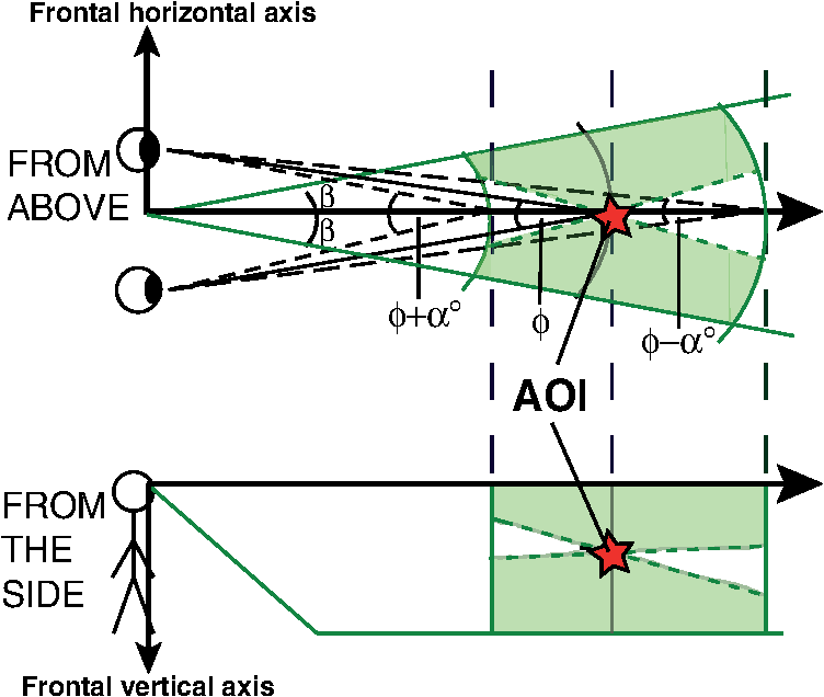 2.1.3.Horizontal frontal positionThe visual space is symmetric along the saggital plane, and thus we can give the same limit for the left and right hemispheres. Foley31 showed that horizontal frontal distance has an effect on distance estimates in stereoscopic depth perception. Foley31 found that in a relative distance task, the user misevaluates the distances. The participants were asked to align points to lie at the apparent frontal plane, and the results showed that position errors increased as a function of horizontal frontal distance from the center. This increase in the position errors was concluded to arise from the distance evaluation of the center point. At greater distances (), the points were perceived to be farther away with respect to the center point (with an error in binocular disparity of approximately 1 arcmin at 10 deg), and at shorter distances (), the points were perceived to be closer with respect to the center point. At shorter distances, the perceptual space is elliptical, and at greater distances, it is hyperbolic. The other guideline for limiting the horizontal frontal position arises from eye and head movements. Eye movements that are within 5 to 10 deg usually require only saccades, and eye movements greater than 10 deg require larger saccades with head movements.32 Unnecessary head movements should be avoided in AR, as inaccuracies in head tracking may have an influence on depth perception. As a result, we can set the condition for the horizontal angle () to be within 10 deg, as illustrated in Fig. 1. 2.1.4.Vertical frontal positionDepth perception is not based solely on commonly known depth cues but also on ground perception and understanding the relative arrangements of parts of the terrain. Gibson33 emphasized the importance of ground perception in space perception. Hence, perceiving the overall layout that is related to the ground can be considered to be a more integral part of distance perception than that related to the ceiling. In fact, more accurate depth judgments have been made with floors than with ceilings.34 This may be because ceiling heights vary by place.35 In addition, most objects in natural scenes located within the action space are below eye level.36 Thus, for visual cueing, it is important to direct the user’s gaze below the horizon, and thus the positions of AAs should be below the eye height but above the ground level (see Fig. 1). The field of view (FOV) of HMDs is usually less than 50 deg in the vertical direction, which limits the perception of the ground. Inconsistent results have been obtained concerning the effect of FOV on depth judgments, depending on the viewing conditions. Wu et al.37 found that with limited FOV, the visibility of ground is lost at near distances, which affects distance judgments. The underestimation of distances was evident when the head was kept still. However, Knapp and Loomis38 did not find this effect on distance when participants were allowed to move their heads freely. It has been noted that when participants are able to move their heads from down to up (from near to far), the limited FOV does not affect distance judgments.37,39 These findings underscore the importance of directing the gaze to the ground when the FOV is limited. 2.1.5.Disparity gradientIn addition to the previously mentioned conditions for stereoscopic AR, the “forbidden zone” arising from the disparity gradient should be taken into account. The disparity gradient () is computed by Eq. (1) where denotes the binocular disparity, and denotes the angular separation between objects.40 A disparity gradient greater than 1 causes diplopic perception.40 Thus, the disparity gradient between the positions of the AOI and the AA should be less than 1 to be stereoscopically fused. In other words, the angular separation between the AA and the AOI should be greater than the binocular disparity.2.2.Interaction of AAs and the Real Environment2.2.1.OcclusionOcclusion is the most dominant depth cue; it is very efficient in cueing ordinal depth.1 Handling occlusion between augmentations and the real world requires a three-dimensional (3-D) reconstruction of the real world. Dynamic occlusion handling requires active measurement of the depth between the user and the augmentation, which is difficult to accomplish accurately. However, rendering occlusions of AAs by static real-world objects can be considered as an efficient approach for anchoring the AAs to the scene based on the dominance of occlusion. 2.2.2.ShadowsShadows have been shown to be efficient tools for visualizing the spatial relationships of objects in computer graphics41,42 and in AR as well.43 The effect of shadows on depth judgments concerning augmented objects has been studied by Wither and Hollerer.8 In their study, however, shadows were cast on an artificial grid plane, not on the real-world ground level. Using an artificial grid plane rather than the real-ground surface most likely reduced the dominance of shadows in the depth perception task. With objects floating in the air, a drop shadow on the ground plane makes the depth interpretation of objects one-dimensional.42 The position of an object can be deduced based on the height at which the shadow hits the ground.42 However, a simulated light source position that is different from that in the real world can be expected to influence depth perception.23 Casting shadows on the ground plane are very sensitive to correct measurement of the ground level. For example, if the ground level is measured as being lower than it really is, then objects are perceived to be closer than they really are based on the position where the shadow hits the actual ground level. 2.2.3.Screen spaceThe real environment, observed through a display, should be as visible as possible to maintain the user’s awareness of the surrounding environment. There are two main reasons for this: (1) the perception of the real world suffers from a loss of screen space due to occlusions by the augmentations, and (2) the user’s attention is divided between the real world and the augmentations. This issue must be taken into account when designing depth cueing in AR. The ratio between seeing the real environment and augmented graphics can be expressed as a see-through–graphics (CT–G) ratio. The CT–G ratio is analogous to the data–ink ratio design rule in information visualization, which applies to the amount of data compared with redundant information. Just as the data–ink ratio should be maximized,44 the CT–G ratio should also be maximized. To keep the CT–G ratio as high as possible, it is important to understand the effect of transparency of the augmentations on depth judgments. Transparency is an integral property of AAs because they are used only to facilitate depth interpretation, and the AAs should occlude the real world as little as possible. Livingston et al.7 studied the effect of semitransparency in the case of x-ray visualization. They found that increasing transparency improved depth judgments in wire frame and fill visualization conditions. Livingston et al.7 also discovered that with constant semitransparency of the planes, stereoscopic viewing improved depth judgments. The AAs should be large enough to facilitate detection of the relative size difference between them and the AOI but small enough to avoid the loss of screen space. Depth detectability at a distance () can be computed according to Eq. (2)16 where is the physical size, and is the acuity with which the change of object size is detected. Thus, there is a clear trade-off between the detectability of relative size as a depth cue and loss of screen space.2.3.ColorThe color of an AA should be the same as that of an AOI to avoid the misperception of depth due to differences in hue, saturation,45 and chromostereopsis.46 It has been shown that similarity in color greatly influences the weight of relative size as a depth cue.47 Thus, using the same color for AAs and AOIs yields the most predictable results. 3.Experiment: Depth Judgments of Augmented Objects3.1.StimuliThe aim of the study was to find to which extent the depth perception of augmented objects could be improved with stereoscopic perception and by overlaying the AAs to the scene. The positions of the AAs were selected according to constraints for position, anchoring, screen space, and color (see Sec. 2). An example of stimulus is shown in Fig. 2. The AOI was a red cone with a semitransparency of 0.6. The height and width of the AOI were 2.3 deg of visual angle. The participants were told that if there were multiple augmented objects in the same scene, then their sizes were equal. This allowed us to study the effect of relative size on depth judgments. 3.2.ProtocolWe used a physical pointer-matching protocol to collect responses from the participants during the depth judgment task. The physical pointer-matching protocol has been used at distances of less than 2 m.18,21 We used physical pointer-matching with Howard–Dolman device in stereo acuity test in Sec. 3.9, which inspired us to scale it up to greater distances. The benefit of a physical pointer is that the judgments are easily measurable from the distance between two physical objects. Another option would have been to use a virtual pointer instead of a physical pointer.9 However, this creates difficulties in establishing ground truth values, as the judged distance is computed using perspective transformation. Usually, the depth estimates beyond personal space are measured by blind walking (e.g., Ref. 13) or a triangulated walking (e.g., Ref. 48) protocols. However, we were interested in the relative distances between the real-world objects and the augmented objects. A physical pointer is especially applicable for such a purpose because the spatial relations between the pointer and other physical objects can be easily measured. In addition, the tests can be conducted over shorter time spans than with the blind walking protocol. The participants were able to wear the HMD between trials, and there was no need to wheel the computer behind the walking participant.11 The physical pointer was created using a string, sheaves, and a red ball with a diameter of 7.2 cm. The string was passed through the sheaves to form a rectangle. The participant was able to adjust the distance of the pointer by pulling the string in two directions with both hands. 3.3.ProcedureThe participants were asked to align the position of the physical pointer (the red ball) with the position of the AOI. The AOI did not have a shadow underneath it (see Fig. 2). In addition to moving the pointer, the participants were asked to evaluate their confidence in their depth judgments on a scale of 1 to 5. The participants were asked to stand, and they were allowed to move freely on an exercise mat. The dimensions of the mat are shown in Fig. 3. After a participant had made a depth judgment, she verbally reported her degree of confidence in the judgment. Next, the experimenter showed a black screen to the participant, read the distance from a measuring tape, and wrote down the judged distance on the paper. Then, the experimenter walked away from the FOV, and a new stimulus was shown to the participant. The stimuli were shown in random order with no same distance in succession. 3.4.VariablesRelative depth cues were evaluated in the experiment under the conditions listed in Table 1. Motion parallax was included in the experiment under all conditions in that the participants were allowed to move to make depth judgments. Table 1Available depth cues with different experimental conditions.
The variables of the experiment are listed in Table 2. The Stereo variable was switched between Mono and Stereo. For the Mono condition, the image from the left camera was shown to both eyes. For the Stereo condition, the images from both cameras were shown to the eyes, and the scene was rendered separately for the left and right eyes. For the AA variable, the scene was shown with or without AAs. The distance to the near AA was 5 m from the participant, and the distance to the far AA was 11 m. The dimensions of the experiment are shown in Fig. 3. For the Height position variable, the height position of the AOI was varied between 0.5 and 1.0 m. The distance to the AOI was varied from 6 to 10 m. The distance range was selected based on the properties of the HMD. We used distances at which the ground level is visible when participants look straight ahead. The furthest distance was selected based on the accuracy of the stereoscopic system. Studying binocular disparity at larger distances would require more accurate calibration and a higher-resolution HMD (see Sec. 3.9). Table 2Independent and dependent variables of the experiment. Participant is considered as random, and other independent variables are considered as within-subjects.
3.5.ParticipantsNineteen participants (10 males and 9 females) were recruited using a university mailing list and a list of visitors of the gym, where the experiments were conducted. The age range of the participants was 21 to 50 years with a mean of 26 years and a standard deviation (SD) of 6.3 years. The stereo acuity without the HMD was tested using the TNO test for stereoscopic vision. One participant was excluded from the test based on an exclusion criterion of 120 arcsec. 3.6.EnvironmentThe experiment was conducted in a gym with dimensions of . Two office screen partitions (1.6-m wide and 1.3-m tall) were placed in the gym (see Figs. 2 and 3). The screen partitions were covered with newspaper pages to offer visual features for tracking. The lighting was approximately 500 lx 3.7.SoftwareThe AR software tracks the camera movements and renders the graphics over video. We used visual tracking based on the same video stream as that shown to the participants. This ensured that the tracking and rendering were in sync with the video. The visual tracking system was based on a 3-D map of salient features in the scene. The features were identified from video frames, and the camera position was estimated from their positions in the image. The map was built with speeded up robust features (SURF) features49 using methods that are standard in 3-D computer vision research.50 We used our own implementation, which was similar to that used by Snavely et al.51 The SURF features were used to initialize the camera position. The map was augmented with good features to track52 for faster tracking after initialization. See Klein and Murray53 for further discussion of tracking methods. The 3-D map was aligned to a measured coordinate system by clicking known points of the scene in reconstructed images. The augmented objects were rendered on a texture, which simulated lens distortion, for better realism. The latency of the camera and tracking system was measured from 685 frames with a timer in the software. The mean latency was 64 ms with an . The latency of the display was 16.67 ms (for a refresh rate of 60 Hz), resulting in total system latency of approximately 81 ms. 3.8.DevicesThe study was conducted using a Trivision ARvision-3D stereoscopic video see-through display. The focal distance of the cameras was set to infinity, and the convergence was set to 5 m. The convergence was roughly adjusted by horizontal shifting, and fine tuning was performed mechanically with a screw. The camera had a resolution of pixels and a frame rate of 60 fps. The separation between the cameras was 6 cm. The camera separation of the HMD was not adjustable, so we were not able to match the camera separation of the HMD to the interpupillary distances (IPDs) of the participants. The IPD range of the participants varied from 58.0 to 68.5 mm with a mean of 62.6 mm. The mismatch between camera separation and IPD might have an effect on depth judgments; however, this mismatch has been found to be minor within action space in virtual environments.54 The HMD had an adjustable interscreen distance, and participants were able to adjust it before the experiment. According to the specifications of the display, the accommodation distance of the screen was 2130 cm. The image from the 3-D camera was cropped to correspond to the FOV of the display (34 deg in the horizontal direction and 25 deg in the vertical direction), resulting in dimensions of pixels for one image. These images were scaled to the HMD, which had a resolution of pixels per eye. The platform was a Dell Precision T3400 with a 3-GHz Intel Core 2 Duo processor and 4 GB of RAM. 3.9.Stereo Acuity Test with the HMD3.9.1.Experimental setupTo characterize the HMD in terms of stereo acuity, we measured the stereo acuity with and without HMD. The participants performed tests with a physical Howard–Dolman apparatus55 bought from Bernell, Mishawaka, Indiana.56 The apparatus consists of two thin white rods (8 mm in diameter) inside a black frame. The distance between the rods is 10 cm. The user is able to move the depth position of the right rod from (forward) to 19 cm (backward). The Howard–Dolman apparatus has been used with the method of constant stimuli and with the method of adjustment (e.g., Ref. 2). In this experiment, we used the method of adjustment, and participants were asked to move the right rod to the same depth plane as the stationary left rod of the Howard–Dolman apparatus. The experiment was conducted with six repetitions, with and without the video see-through HMD, by viewing the apparatus from a 3-m distance. For half of the trials, the initial position of the moveable rod was set to the near end (21 cm in front of the center point), and for the other half of the trials, the initial position was set to the far end (19 cm behind the center point). Half of the participants performed the test with the video see-through HMD and then without the HMD. The other half performed the tests in the reverse order. 3.9.2.ResultsThe SD without the HMD was 0.25 arcmin, and the SD with the HMD was 1.43 arcmin. Statistical analysis was conducted using mixed analysis of variance (ANOVA) considering order as between-subjects independent variable and HMD, initial position, and repetition as within-subjects independent variables. The dependent variables were signed and absolute errors. Livingston et al.20 detected a significant effect of initial position on the signed error of depth judgments, concerning virtual objects with optical see-through HMD. Figure 4(a) shows a similar trend with physical objects; however, we found neither statistically significant main effect of initial position on signed error [, , ] nor interaction between HMD and initial position on signed error [, , ]. Wilner et al.57 studied the effect of initial position on depth judgments without HMD. They found that for four of eight participants, the initial position affected signed error. Thus, no clear evidence exists that the initial position affects the signed error. Fig. 4Influence of viewing condition on errors. Differences in signed error for the back and front initial positions (a) and absolute error for two orders of viewing conditions (b). The error bars represent standard errors.  We found a statistically significant main effect of HMD on absolute error [, , ]. The main effects for order, initial position, and repetition on absolute error were not statistically significant. Figure 4(b) shows that the absolute error with HMD was lower when the test was conducted last with HMD, but the interaction between HMD and order on absolute error [, , ] was not statistically significant. The Howard–Dolman apparatus proved to be applicable to testing stereoscopic perception with the HMD. However, the distance between the near and the far ends of the Howard–Dolman apparatus should be larger to permit larger offsets in the depth judgments. The maximum depth judgment offsets that a participant was able to make were arcmin in the front and 4.45 arcmin in the back. This limitation might have affected the results, as the participants were able to learn to adjust the position approximately to the center by moving the rod to the near and far ends and then halving the distance. Using the Howard–Dolman apparatus with the method of constant stimuli would have removed this effect, and thus it is a preferred method for measuring stereo acuity with HMD in future studies. 4.Results4.1.Depth JudgmentsStatistical analysis was conducted using a repeated-measure ANOVA for mean values of repetitions. The Distance variable had more than two conditions (), and thus we had to test the assumption of sphericity of Distance for signed and absolute errors. Mauchly’s tests on signed and absolute errors showed that the assumptions of sphericity were violated (). Therefore, the degrees of freedom were corrected using Greenhouse–Geisser estimates of sphericity. The depth judgments are shown in Fig. 5, and the slopes are presented in Table 3. Two three-way interaction effects were found. All main effects related to the following three-way interactions are statistically significant (). Fig. 5Mean depth judgments as a function of actual distance. We fitted lines to the judgments using linear regression. The error bars represent standard errors. 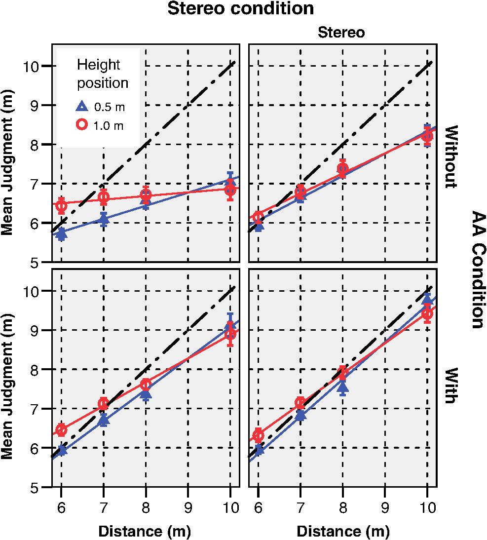 Table 3The slopes and R2 values from linear regression for different visualization conditions and object height positions.
First, we found a three-way interaction between Stereo, AA, and Distance variables on signed [, , ] and absolute [, , ] errors. The depth judgments improved cumulatively toward the veridical for Stereo and with AAs conditions. Under Stereo with AAs condition, the signed and absolute errors increase the least as a function of Distance. The signed error was mostly negative, which indicates underestimation of distance (i.e., the depth judgments were lower than the veridical values). Second, a three-way interaction effect was found between Stereo, Distance, and Height position variables on absolute error [, , ]. The interaction effect between Stereo, Height position, and Distance can be seen from Fig. 5: increment of Height position from 0.5 to 1.0 m increases the absolute error more under Mono condition than under the Stereo condition as a function of Distance. Under Mono condition at closer distances (6 to 8 m), the depth judgments were greater when the Height position of the AOI was 1 m. Then, the AOI was viewed against the background. When the Height position of the AOI was 0.5 m, it was viewed against the floor at distances from 6 to 8 m. At 10 m, all stimuli were perceived against the background and the height effect was not present. The Height position has an effect on slopes for the different visualization conditions considered. When the object was higher, the slope was reduced for every visualization condition, as can be seen from Table 3. 4.2.ConfidenceFigure 6(a) shows the confidence of depth judgments with different conditions. The Stereo variable had a statistically significant effect on the degree of confidence in depth judgments [, , ]. For the Mono condition, the degree of confidence was lower than that for the Stereo condition. The AA variable did not have a statistically significant effect on the degree of confidence [, , ]. Fig. 6Participants’ degree of confidence in depth judgments for various conditions (a) and distances (b). The error bars represent standard errors. 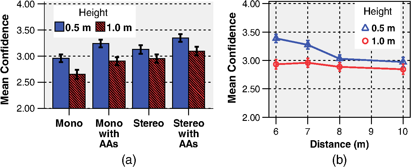 Figure 6(b) shows an interaction effect between Distance and Height position on confidence [, , ]. The height has more effect in confidence judgments at near distances than at far distances. The higher the object appeared to be, the less confident the participants were about their judgments. This finding underscores the importance of the ground to depth judgments within the action space. With Stereo condition, the confidence judgments were less affected by the height position than with the Mono condition, which was also the case with the absolute error of depth judgments. However, interaction effect between Stereo and Height position on confidence did not reach statistical significance [, , ]. 5.DiscussionStereoscopic perception in video see-through AR in this distance range has not been previously systematically studied. The experiment contributed with the finding that the stereo acuity with the video see-through HMD was worse by a factor of over 5 compared with that without the HMD. The findings of the main experiment indicate that additional depth cues can be used to improve the accuracy of stereoscopic depth perception in video see-through AR. We successfully used relative size for this purpose, as relative size and binocular disparity integrated additively. The relative size seems to help in scaling the egocentric distance, which facilitates the perception of disparity. Allison et al.22 found a similar influence of monocular depth cues with natural viewing within the action space. The combination of binocular disparity and relative size is very efficient because binocular disparity is very accurate at short distances and the depth threshold of relative size remains constant at greater distances.1 Overall, these results give insights for depth perception in stereoscopic AR applications. The slopes of depth judgments varied from 0.09 to 0.95 depending on the available depth cues. Beyond this selected distance range (), the effect of stereoscopic perception on depth judgments is more likely to be reduced, as the slopes for stereoscopic perception (0.51 and 0.56) seem to decline at a distance of 8 m. Grechkin et al.13 found no declination of slope (0.7) at distances from 6 to 18 m when objects were aligned with the ground level. In this study, with stereoscopic perception combined with relative size, declination of the slope did not occur. These results are consistent with those of a previous study,24 in which the effect of relative size was found to have a similar influence. In addition to binocular disparity and relative size, the height position of objects affected depth judgments. The height in the visual field was not available as a depth cue in its natural form because the objects were “floating” in the air. In addition, the AAs had different height positions above the ground plane than the AOI. Height in the visual field has a clear influence on absolute depth judgments.1,25 Thus, the depth judgments could have been improved by setting the same height position for the AAs and the AOI. However, this limits the possible space for AAs. In AR, Dey et al.15 observed an effect of height in the visual field on ordinal depth perception. To assess the effect of height in the visual field on depth judgments more deeply, the participants should also have been asked to judge the height position of the object, as in the study by Ooi et al.25 There are many properties that can be manipulated between AOI and AAs such as size, number, and transparency. These were combined in the theoretical part of this study in a CT–G ratio. The effects of the factors that influence the ratio and depth perception accuracy could be subjects of future study. The number of AAs is also an interesting issue for future research. In this study, we used two AAs. Adding only one AA to close to or far from the AOI might have offered enough information about depth judgments in our experiment. The distances between the AAs and the AOI can be varied, but the AAs themselves can also be varied. This offers more possibilities; for example, the size of the AAs does not have to be the same as that of the AOI. The similarity in surfaces between the AAs and the AOI can offer enough cues for depth interpretation, and the AAs and the AOI can differ in their spatial properties (e.g., shape and size), which allows a more malleable approach. The AA and AOI should differ to avoid confusing the AOI and AAs. The object shape can be used to distinguish between the AAs and the AOI. Differentiating objects by shape is justified. Sousa et al.47 found that variation in shapes did not affect the weight of using size as a relative depth cue between multiple objects. Differences in colors and orientations decreased the weight of the relative size cue. This study suffers from the limitation that we were not able to measure the contrast of the HMD. Thus, we cannot systematically examine the effect of contrast between the AAs and the real world based on depth judgments. Contrast improves stereo acuity,58 but higher contrast makes objects appear closer.59 The contrast effect on stereo acuity is saturated beyond 21 dB,58 and more contrast between AAs and real-world background objects should not be present. In addition, the effect of a texture gradient was not investigated in this study. Hou60 showed that texture density affects the alignment accuracy of a stereoscopic pointer. A denser texture yields more accurate results. Thus, highly textured AAs should be used in tasks that require high accuracy. However, texture density is limited by the resolution of the display, and thus, the perception of fine texture decreases at the far limit of the action space. In addition, even though our tracking system provided no negative feedback, quantifying the errors emerging from tracking (e.g., latency and registration accuracy) would improve the possibility of studying the effect of motion parallax on depth judgments. McCandless et al.61 examined the effect of latency on depth judgments within personal space with monocular viewing. They found that compression of perceived depth occurred when latency was increased. To the best of our knowledge, however, no study has been conducted on the effect of tracking errors on depth judgments within the action space. This research gap should be filled in future studies. 6.ConclusionsDepth judgment within the action space was investigated using a stereoscopic video see-through HMD. We studied the effects of depth cues on depth judgments of augmented objects above ground plane within distances from 6 to 10 m. Stereoscopic perception improved the depth judgments of objects significantly compared with monoscopic perception. In addition, the relative size cue increased the accuracy of depth judgments significantly. Moreover, the depth judgments were the closest to veridical depth when binocular disparity and relative size were combined. The relative size cue was created by adding AAs to the scene according to constraints deduced from theoretical considerations. This approach is applicable when visual interaction between the real environment and the AOI is not possible such as in situations where the AOI is viewed from perspectives that hide the ground plane. AcknowledgmentsWe wish to thank Unisport Meilahti for cooperating in arranging the availability of the gym used in the experiments and the three anonymous reviewers for helpful comments on this manuscript. The study was funded by the MIDE (Multidisciplinary Institute of Digitalization and Energy) program. ReferencesJ. E. CuttingP. M. Vishton,
“Perceiving layout and knowing distances: the integration, relative potency, and contextual use of different information about depth,”
Handbook of Perception and Cognition, 69
–117 Academic Press, San Diego, CA
(1995). Google Scholar
J. P. Rollandet al.,
“Method of adjustments versus method of constant stimuli in the quantification of accuracy and precision of rendered depth in head-mounted displays,”
Presence, 11
(6), 610
–625
(2002). http://dx.doi.org/10.1162/105474602321050730 PSENEG 1054-7460 Google Scholar
T. Oskamet al.,
“Fast and stable color balancing for images and augmented reality,”
in Int. Conf. 3D Imaging, Modeling, Processing, Visualization & Transmission,
49
–56
(2012). Google Scholar
L. XuetingT. Ogawa,
“A depth cue method based on blurring effect in augmented reality,”
81
–88 ACM Press, New York
(2013). Google Scholar
J. P. RollandH. Fuchs,
“Optical versus video see-through head-mounted displays in medical visualization,”
Presence, 9
(3), 287
–309
(2000). http://dx.doi.org/10.1162/105474600566808 PSENEG 1054-7460 Google Scholar
A. Takagiet al.,
“Development of a stereo video see-through HMD for AR systems,”
in IEEE and ACM Int. Symposium on Augmented Reality,
68
–77
(2000). Google Scholar
M. A. Livingstonet al.,
“Resolving multiple occluded layers in augmented reality,”
in IEEE/ACM Int. Symposium on Mixed and Augmented Reality,
56
–65
(2003). Google Scholar
J. WitherT. Hollerer,
“Pictorial depth cues for outdoor augmented reality,”
in IEEE Int. Symposium on Wearable Computers,
92
–99
(2005). Google Scholar
J. E. Swan IIet al.,
“A perceptual matching technique for depth judgments in optical, see-through augmented reality,”
in Virtual Reality Conf.,
19
–26
(2006). Google Scholar
J. Swan IIA. JonesE. Kolstad,
“Egocentric depth judgments in optical, see-through augmented reality,”
IEEE Trans. Visual. Comput. Graph., 13
(3), 429
–442
(2007). http://dx.doi.org/10.1109/TVCG.2007.1035 TVCG 1077-2626 Google Scholar
J. A. Joneset al.,
“The effects of virtual reality, augmented reality, and motion parallax on egocentric depth perception,”
in Symp. Appl. Percept. Graph. Visual.,
9
–14
(2008). Google Scholar
M. A. Livingstonet al.,
“Indoor vs. outdoor depth perception for mobile augmented reality,”
in IEEE Virtual Reality Conf.,
55
–62
(2009). Google Scholar
T. Y. Grechkinet al.,
“How does presentation method and measurement protocol affect distance estimation in real and virtual environments?,”
ACM Trans. Appl. Percept., 7
(4), 1
–18
(2010). http://dx.doi.org/10.1145/1823738 1544-3558 Google Scholar
A. DeyA. CunninghamC. Sandor,
“Evaluating depth perception of photorealistic mixed reality visualizations for occluded objects in outdoor environments,”
in ACM Symposium on Virtual Reality Software and Technology,
211
–218
(2010). Google Scholar
A. Deyet al.,
“Tablet versus phone: depth perception in handheld augmented reality,”
in IEEE Int. Symposium on Mixed and Augmented Reality,
187
–196
(2012). Google Scholar
S. Nagata,
“How to reinforce perception of depth in single two-dimensional pictures,”
Pictorial Communication in Virtual and Real Environments, 527
–544 Taylor & Francis, Mahwah, New Jersey
(1991). Google Scholar
J. P. Rollandet al.,
“Quantification of adaptation to virtual-eye location in see-thru head-mounted displays,”
56
–66 IEEE Computer Society, Washington, DC
(1995). Google Scholar
S. R. EllisB. M. Menges,
“Localization of virtual objects in the near visual field,”
Hum. Factors, 40
(3), 415
–431
(1998). http://dx.doi.org/10.1518/001872098779591278 HUFAA6 0018-7208 Google Scholar
V. JurgensA. CockburnM. Billinghurst,
“Depth cues for augmented reality stakeout,”
in Proc. 7th ACM SIGCHI New Zealand Chapter’s Int. Conf. Computer-Human Interaction: Design Centered HCI,
117
–124
(2006). Google Scholar
M. A. LivingstonA. ZhumingJ. W. Decker,
“A user study towards understanding stereo perception in head-worn augmented reality displays,”
in IEEE Int. Symposium on Mixed and Augmented Reality,
53
–56
(2009). Google Scholar
G. SinghJ. E. Swan IIJ. A. Jones,
“Depth judgment measures and occluding surfaces in near-field augmented reality,”
in Symp. Appl. Percept. Graph. Visual.,
149
–156
(2010). Google Scholar
R. S. AllisonB. J. GillamE. Vecellio,
“Binocular depth discrimination and estimation beyond interaction space,”
J. Vision, 9
(1), 10.1
–14
(2009). http://dx.doi.org/10.1167/9.1.10 1534-7362 Google Scholar
E. KruijffJ. E. SwanS. Feiner,
“Perceptual issues in augmented reality revisited,”
in IEEE Int. Symposium on Mixed and Augmented Reality,
3
–12
(2010). Google Scholar
M. Kytöet al.,
“Improving relative depth judgments in augmented reality with auxiliary augmentations,”
ACM Trans. Appl. Percept., 10
(1), 1
–22
(2013). http://dx.doi.org/10.1145/2422105 1544-3558 Google Scholar
T. L. OoiB. WuZ. J. He,
“Distance determined by the angular declination below the horizon,”
Nature, 414
(6860), 197
–200
(2001). http://dx.doi.org/10.1038/35102562 NATUAS 0028-0836 Google Scholar
C. M. Schor,
“Spatial constraints of stereopsis in video displays,”
Pictorial Communication in Virtual and Real Environments, 546
–557 Taylor & Francis, Bristol, PA
(1993). Google Scholar
I. P. HowardB. J. Rogers, Perceiving in Depth. Volume 2: Stereoscopic Vision, 635 Oxford University Press, New York
(2012). Google Scholar
C. SchorI. Wood,
“Disparity range for local stereopsis as a function of luminance spatial frequency,”
Vision Res., 23
(12), 1649
–1654
(1983). http://dx.doi.org/10.1016/0042-6989(83)90179-7 VISRAM 0042-6989 Google Scholar
M. Lambooijet al.,
“Visual discomfort and visual fatigue of stereoscopic displays: a review,”
J. Imaging Sci. Technol., 53
(3), 030201
(2009). http://dx.doi.org/10.2352/J.ImagingSci.Technol.2009.53.3.030201 JIMTE6 1062-3701 Google Scholar
T. Shibataet al.,
“The zone of comfort: predicting visual discomfort with stereo displays,”
J. Vision, 11
(8), 11:1
–29
(2011). http://dx.doi.org/10.1167/11.8.11 1534-7362 Google Scholar
J. M. Foley,
“Binocular distance perception,”
Psychol. Rev., 87
(5), 411
–434
(1980). http://dx.doi.org/10.1037/0033-295X.87.5.411 PSRVAX 0033-295X Google Scholar
K. W. Arthur,
“Effects of field of view on performance with head-mounted displays,”
University of North Carolina(2000). Google Scholar
J. Gibson, The Perception of the Visual World, 235 Houghton Mifflin, Oxford, England
(1950). Google Scholar
Z. BianG. J. Andersen,
“Environmental surfaces and the compression of perceived visual space,”
J. Vision, 11
(7), 1
–14
(2011). http://dx.doi.org/10.1167/11.7.4 1534-7362 Google Scholar
W. B. ThompsonV. DildaS. H. Creem-Regehr,
“Absolute distance perception to locations off the ground plane,”
Perception, 36
(11), 1559
–1571
(2007). http://dx.doi.org/10.1068/p5667 PCTNBA 0301-0066 Google Scholar
Z. YangD. Purves,
“A statistical explanation of visual space,”
Nat. Neurosci., 6
(6), 632
–640
(2003). http://dx.doi.org/10.1038/nn1059 NANEFN 1097-6256 Google Scholar
B. WuT. L. OoiJ. H. Zijiang,
“Perceiving distance accurately by a directional process of integrating ground information,”
Nature, 428 73
–77
(2004). http://dx.doi.org/10.1038/nature02350 NATUAS 0028-0836 Google Scholar
J. M. KnappJ. M. Loomis,
“Limited field of view of head-mounted displays is not the cause of distance underestimation in virtual environments,”
Presence Teleoperators Virtual Environ., 13
(5), 572
–577
(2004). http://dx.doi.org/10.1162/1054746042545238 1054-7460 Google Scholar
S. H. Creem-Regehret al.,
“The influence of restricted viewing conditions on egocentric distance perception: implications for real and virtual environments,”
Perception, 34
(2), 191
–204
(2005). http://dx.doi.org/10.1068/p5144 PCTNBA 0301-0066 Google Scholar
P. BurtB. Julesz,
“A disparity gradient limit for binocular fusion,”
Science, 208
(4444), 615
–617
(1980). http://dx.doi.org/10.1126/science.7367885 SCIEAS 0036-8075 Google Scholar
L. R. WangerJ. A. FerwerdaD. P. Greenberg,
“Perceiving spatial relationships in computer-generated images,”
IEEE Comput. Graph. Appl., 12
(3), 44
–58
(1992). http://dx.doi.org/10.1109/38.135913 ICGADZ 0272-1716 Google Scholar
G. S. Hubonaet al.,
“The relative contributions of stereo, lighting, and background scenes in promoting 3D depth visualization,”
ACM Trans. Comput. Hum. Interaction (TOCHI), 6
(3), 214
–242
(1999). http://dx.doi.org/10.1145/329693.329695 1073-0516 Google Scholar
N. SuganoH. KatoK. Tachibana,
“The effects of shadow representation of virtual objects in augmented reality,”
in IEEE and ACM Int. Symposium on Mixed and Augmented Reality,
76
–83
(2003). Google Scholar
E. R. Tufte, The Visual Display of Quantitative Information, Graphics Press, Cheshire, CT
(1983). Google Scholar
H. Egusa,
“Effects of brightness, hue, and saturation on perceived depth between adjacent regions in the visual field,”
Perception, 12
(2), 167
–175
(1983). http://dx.doi.org/10.1068/p120167 PCTNBA 0301-0066 Google Scholar
J. J. Vos,
“The color stereoscopic effect,”
Vision Res., 6
(1), 105
–107
(1966). http://dx.doi.org/10.1016/0042-6989(66)90019-8 VISRAM 0042-6989 Google Scholar
R. SousaJ. B. J. SmeetsE. Brenner,
“The effect of variability in other objects’ sizes on the extent to which people rely on retinal image size as a cue for judging distance,”
J. Vision, 12
(10), 6:1
–8
(2012). http://dx.doi.org/10.1167/12.10.6 1534-7362 Google Scholar
W. B. Thompsonet al.,
“Does the quality of the computer graphics matter when judging distances in visually immersive environments?,”
Presence Teleoperators Virtual Environ., 13
(5), 560
–571
(2004). http://dx.doi.org/10.1162/1054746042545292 1054-7460 Google Scholar
H. BayT. TuytelaarsL. Van Gool,
“Surf: speeded up robust features,”
in Computer Vision ECCV 2006,
404
–417
(2006). Google Scholar
R. HartleyA. Zisserman, Multiple View Geometry in Computer Vision, Cambridge University Press, Cambridge, United Kingdom
(2000). Google Scholar
N. SnavelyS. M. SeitzR. Szeliski,
“Photo tourism: exploring photo collections in 3D,”
ACM Trans. Graph., 25
(3), 835
–846
(2006). http://dx.doi.org/10.1145/1141911 1548-4580 Google Scholar
J. ShiC. Tomasi,
“Good features to track,”
in Proc. CVPR’94,
593
–600
(1994). Google Scholar
G. KleinandD. Murray,
“Parallel tracking and mapping for small AR workspaces,”
in IEEE and ACM Int. Symposium on Mixed and Augmented Reality,
1
–10
(2007). Google Scholar
P. Willemsenet al.,
“Effects of stereo viewing conditions on distance perception in virtual environments,”
Presence Teleoperators Virtual Environ., 17
(1), 91
–101
(2008). http://dx.doi.org/10.1162/pres.17.1.91 1054-7460 Google Scholar
H. J. Howard,
“A test for the judgment of distance,”
Trans. Am. Ophthalmol. Soc., 17 195
–235
(1919). TAOSAT 0065-9533 Google Scholar
Bernell, “Howard-Dolman Type Test,”
(2013) http://www.bernell.com/product/2013/126 April ). 2013). Google Scholar
B. I. WilnerF. W. WeymouthM. J. Hirsch,
“Influence of initial position of rods in Howard-Dolman test,”
Arch. Ophthalmol., 44
(3), 365
–369
(1950). http://dx.doi.org/10.1001/archopht.1950.00910020374003 AROPAW 0003-9950 Google Scholar
D. L. HalpernR. B. Blake,
“How contrast affects stereoacuity,”
Perception, 17
(4), 483
–495
(1988). http://dx.doi.org/10.1068/p170483 PCTNBA 0301-0066 Google Scholar
R. P. O’SheaS. G. BlackburnH. Ono,
“Contrast as a depth cue,”
Vision Res., 34
(12), 1595
–1604
(1994). http://dx.doi.org/10.1016/0042-6989(94)90116-3 VISRAM 0042-6989 Google Scholar
M. Hou,
“User experience with alignment of real and virtual objects in a stereoscopic augmented reality interface,”
in Centre for Advanced Studies on Collaborative Research,
(2001). Google Scholar
J. W. McCandlessS. R. EllisB. D. Adelstein,
“Localization of a time-delayed, monocular virtual object superimposed on a real environment,”
Presence (Cambridge, Mass.), 9
(1), 15
–24
(2000). http://dx.doi.org/10.1162/105474600566583 1054-7460 Google Scholar
BiographyMikko Kytö received his MSc degree from Helsinki University of Technology, Finland, in 2009. He is currently finalizing his PhD degree at Aalto University School of Science in the Department of Media Technology. His research interests include perceptual issues in augmented reality, stereoscopy, and viewing experience of S3D contents. Aleksi Mäkinen is a student of computer science and engineering at Aalto University School of Science. He has worked as a research assistant working on structure from motion and augmented reality-related problems in the Department of Media Technology at Aalto University. He is currently a junior developer at ZenRobotics Ltd. Timo Tossavainen received his MSc and PhD degrees in computer science from the University of Tampere, in 1999 and 2006, respectively. He previously worked at the University of Tampere, VTT Technical Research Centre of Finland, and Aalto University. He is currently a senior scientist at ZenRobotics Ltd. His research interests include 3D computer vision, virtual and augmented realities, and machine learning. Pirkko Oittinen is a full professor at Aalto University School of Science in the Department of Media Technology. Her Visual Media Research Group has the mission of advancing visual technologies and raising the quality of visual information to create enhanced user experiences in different usage contexts. Her current research topics include still image, video and 3-D image quality, content repurposing for mobile platforms, and media experience arising from human–media interaction. |
||||||||||||||||||||||||||||||||||||||||||||||||||||||||||||||||||||||||||||||||||||||||||||


