|
|
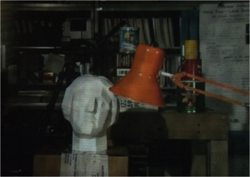
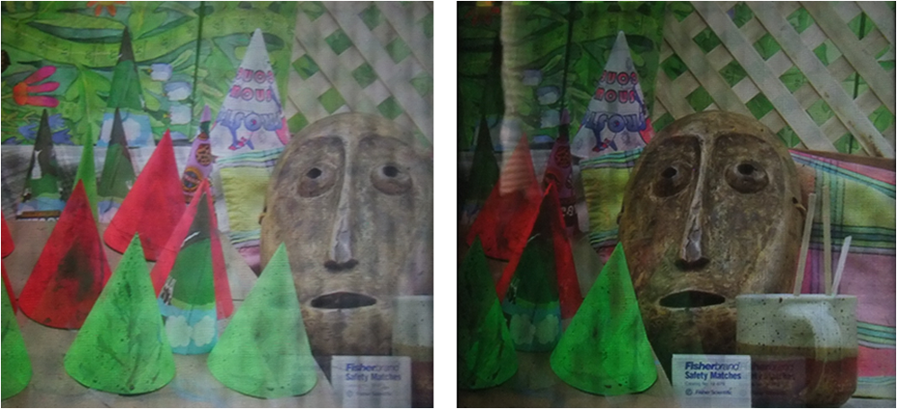
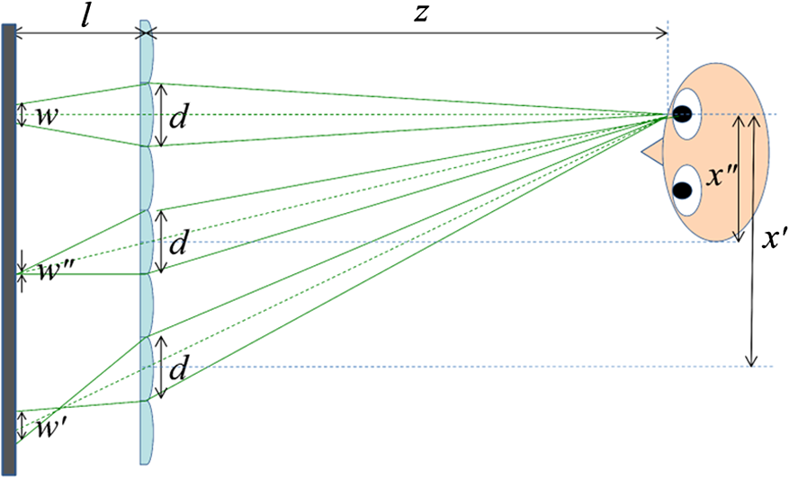
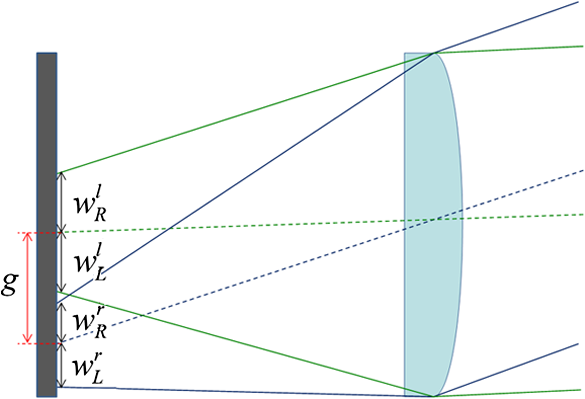
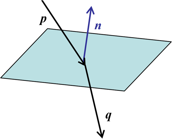
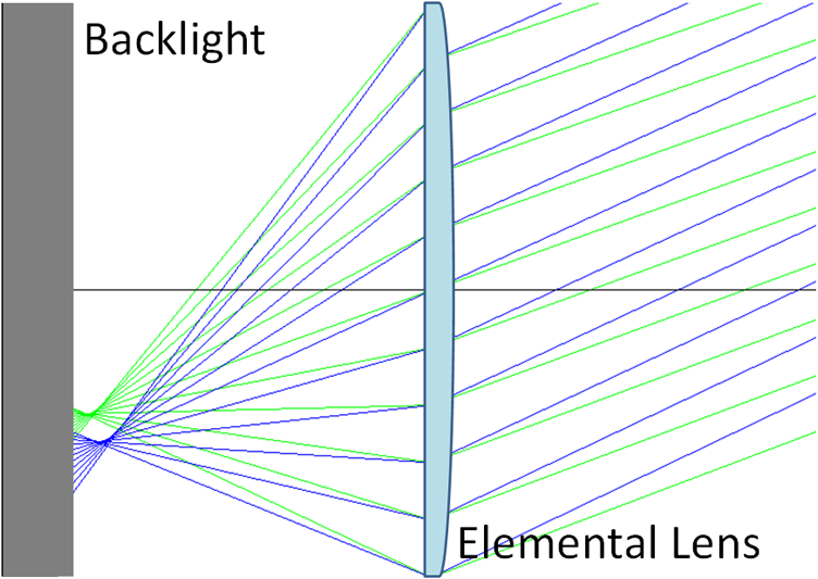
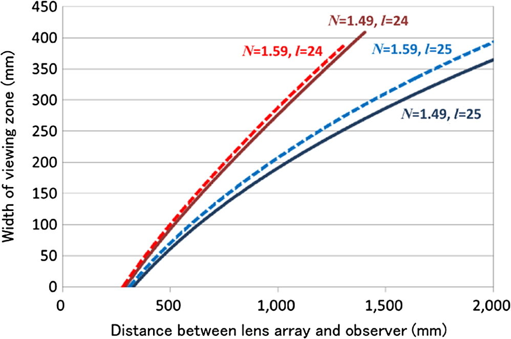
1.IntroductionTime-division multiplexing is one of the major methods to attain a stereoscopic display. With the advancement of liquid crystal display (LCD) technologies, LCD panels that can attain a short response time (120 Hz or faster) have been developed, which has enabled commercialization of three-dimensional (3-D) LCD TV sets based on the time-division multiplexing coupled with shutter glasses. LCD panels operating at high refresh rates can also be applied to autostereoscopic displays with high resolution. Most autostereoscopic displays developed so far are based either on parallax barrier technology or on lenticular lens technology. Though multiple display pixels under a single aperture or lens can create multiple viewing zones, the cost to this is a significant loss in resolution. The time-division multiplexing has enabled the presentation of a stereoscopic image whose resolution is the same as that of the display panel. One of the simplest ways to realize high resolution autostereoscopy with time-division multiplexing is to use an active parallax barrier.1–3 Fixed parallax barrier with two viewpoints reduces the resolution of the image by half. By alternating the position of the parallax barrier and the image on the display panel synchronously at a high refresh rate, a full resolution 3-D image can be delivered to the viewer. Another way to realize high resolution autostereoscopy is to use a directional backlight using a light guide film and a pair of light sources.4–6 The autostereoscopy can be realized by switching the light sources and the image on the display panel synchronously. A common drawback of the time-division multiplexing autostereoscopic displays introduced so far is the limited number of viewers. Basically, they can display a stereoscopic image to a single viewer only. Though there have been a few trials to increase the number of possible viewers,7,8 the viewing position is still limited. One way to achieve a directional backlight for multiple viewpoints is to use a subpixel-size light source coupled with a lenticular lens.9 This method, however, cannot secure many viewpoints because of the limitation on the microfabrication of the subpixel light source. A directional backlight with more viewing positions can be realized by the use of a large aperture convex lens.10,11 The same optics can also be attained by using a concave mirror.12 These systems, however, require a deep optical distance. To solve the problem of display thickness, Hattori proposed the use of a coarse convex lens array in place of a large aperture convex lens.13–16 This method, however, is not practical because the obtained 3-D image includes a distinct seam of the lens array. Ishizuka and Kakeya17 solved this problem by placing a vertical diffuser in front of the convex lens array. One problem of the directional backlight composed of a convex lens array and a dot matrix light source is the defocusing and field curvature of the lens. These factors restrict the viewing zone of the autostereoscopic image. In this paper, the viewing zone of the autostereoscopic display using a convex lens array is analyzed based on optical simulations. 2.Directional Backlight Using a Convex Lens ArrayThe principle of a directional backlight using a convex lens array is shown in Fig. 1. When the dot matrix light sources are placed behind the convex lens array so that the distance between them may be equal to the focal distance of the elemental lens of the lens array, collimated directional light is realized. By changing the position of the luminous light source, the orientation of the directional light can be controlled. When the directional backlight to each eye alternates synchronously with the alternation of left-eye and right-eye images on the LCD panel, the viewer can see a stereoscopic image without wearing special goggles. By increasing the number of light sources, multiple viewers can enjoy the stereoscopic image at the same time. The problem of the system shown in Fig. 1 is poor image quality due to the distinct seam of the coarse lens array as shown in Fig. 2. Also the intensity of the image is not uniform because the light going through the peripheral part of the elemental lenses is weaker than the light going through the center of the elemental lenses. To remove the seam of the lens and the nonuniformity of intensity of the image to be presented, the use of a hexagonal lens array and a vertical diffuser, as shown in Fig. 3, is effective. The diffuser is inserted to blur the seam and nonuniform intensity of the lens array. In the prototype system, a fine lenticular lens (0.02-mm radius, 0.04-mm pitch) is used as the diffuser and a pair of 24-in. Thin film transistor (TFT) panels (BenQ XL2420T), whose resolution is , is used as the front panel and the backlight panel to attain synchronized 120 Hz control. The antiglare film and the polarization films facing the other LCD panel are removed to let the light pass straight. Note that the LCD panels with large pixel apertures should be chosen for this system so that the effect of diffraction may not cause crosstalk. Fig. 3Autostereoscopy with a directional backlight using a convex lens array and a vertical diffuser.  The image attained by the prototype system in Fig. 3 is shown in Fig. 4. To maintain autostereoscopy, the rays into the left eye and the right eye of the viewer should be separated. The ray diffused only in the vertical direction can maintain the directionality of the light in the horizontal direction, which does not destroy stereopsis. Thus, smooth stereoscopic images with little crosstalk are observed as shown in Fig. 5. In reality, however, the directional backlight using a convex lens array has two major optical problems when it is applied to autostereoscopic displays. One is the problem of defocusing and the other is the field curvature of the lens. Figure 6 illustrates how these two problems emerge. (Note that the effect of the vertical diffuser can be neglected because it does not affect the optical pathway in the horizontal direction.) To make the whole image uniformly bright, the light rays to the eye should go through all portions of the lens. In other words, the area where the light rays from the eye impinge on the light source plane through the lens array has to be all luminous. In case the distance between the lens and the light source plane is the same as the focal distance of the lens, the luminous area has to be wider when the distance between the observer and the lens becomes shorter. This is the problem caused by the defocusing of the lens. Here, the width increases as the diameter of the lens becomes larger. ( has to be large enough to maintain the number of observable viewpoints.) In case the distance between the eye and the optical axis of the elemental lens is large, the light ray from the light source to the eye becomes strongly oblique, which leads to steep field curvature. Because of the field curvature, the light ray converges far from the light source and widens as a result. When the angle of the light ray is moderate, the effects of defocusing and field curvature cancel each other out and the light converges most on the display plane. When is excessively large, the luminous areas for the left eye and the right eye overlap with each other, which leads to the emergence of crosstalk. To avoid crosstalk, should be shorter than the gap between the centers of light sources for both eyes, which is given by where is the distance between the right eye and the left eye (Fig. 7). To be precise, crosstalk is avoided when the right side width of the backlight area for the right eye plus the left side width of the backlight area for the left eye is smaller than the gap , as shown in Figure 8.3.Analysis of the Viewing ZoneThe discussion in the previous section suggests that a couple of methods can be applicable to maintain a large viewing zone free from crosstalk. One possibility is to use a lens made of material whose refractive index is large so that the field curvature may be shallower. Another possibility is to adjust the distance between the lens and the light source plane. When is short, the effect of field curvature can be reduced in the peripheral part of the display as the light source plane approaches the light condensing points. On the other hand, the defocusing effect becomes stronger in the central portion of the display. As long as the defocusing does not reach the level to cause crosstalk, however, a smaller is expected to contribute to the expansion of the viewing angle. To investigate the viewing zone free from crosstalk, numerical optical simulation is carried out in the case where , , , and . These parameters are based on the specifications of the prototype system shown in Fig. 3. Refracted light ray in the optical simulation is given by where is the incident light ray and is the normal vector of the lens surface. Here, note that , , and should be unit vectors in the above calculation. The directions of vectors are illustrated in Fig. 9. Since we use Fresnel lenses for elemental lenses and the large aperture lens, we can ignore the thickness of lenses. The Fresnel lens that we use has a focal point on the flat side of the lens. This type of Fresnel lens has the surface curvature whose normal vector is given by at (), where (0, 0) is the center of the lens and is the focal distance of the lens.18 Validity of this optical simulation has been confirmed in the study of coarse integral volumetric imaging.19,20 An example of the optical simulation based on the above equations is shown in Fig. 10. Figures 11 and 12 show calculated by the optical simulations when and , respectively.As shown in Fig. 11, becomes smaller as the distance between the eye and the lens array plane becomes larger, while also becomes smaller. When the distance between the eye and the optical axis of the elemental lens is large, has to be large to make smaller than . The distance gives the least because the effect of defocusing and field curvature is balanced. When is smaller than the focal distance , the curve of is shifted upwards for small and downwards for large , as shown in Fig. 12. This is caused by the increase of the defocusing effect. Here, the curve is reversed after reaches zero. With this shift, the width becomes smaller than the gap at small even when is large while it leads to larger than for a combination of small and large . Figure 13 shows the results of optical simulation on the width of the viewing zone where the backlight areas for the right eye and the left eye do not overlap with each other on the whole display plane. Here, the width of the display plane is set to 286 mm (13 elemental lenses whose diameter is 22 mm), which is based on the specification of the prototype system shown in Fig. 3. The width of the viewing zone is defined as the length of the allowed head movement in the lateral direction to avoid crosstalk. As shown in the figure, the viewing angle is not wide when . When , the viewing angle is widened, whereas the viewing zone becomes shallower. (The point where the line is cut off indicates the limit of the range where crosstalk can be avoided in the central viewpoint.) Also it is confirmed that the use of a lens made up of material with a large refractive index widens the viewing angle. We carried out a hardware experiment to confirm the validity of the above optical simulations. BenQ XL2420T, which was used for the dot matrix light source in the prototype system, was used in this experiment also. The backlight area was divided into two portions, as shown in Fig. 14 for simplicity. The backlight areas for the left eye and the right eye were illuminated with green and magenta, respectively, and the diffuser and the front LCD panel were removed to see the crosstalk clearly. In the experiment, was fixed to 670 mm and the images observed by the left eye and the right eye were taken by FujiFilm Real3D W3, whose baseline is 75 mm. The lens parameters were as follows: ; ; . With this configuration, the optical simulator predicts that the backlight for the left eye intrudes into the right eye when the distance between the center of the eyes and the elemental lens is larger than 170 mm for and 200 mm for . Figure 15 shows the result of the hardware experiment. When , the magenta backlight intrudes into the elemental lenses whose centers are 167 mm or more away from the center of the camera (the midpoint of the two lenses). This value is close to the result of the optical simulation. When , the magenta backlight intrudes into the elemental lenses whose centers are 200 mm or more away from the center of the camera. This value coincides with the result of the optical simulation. Thus, the credibility of the optical simulation and the validity of the proposed system to expand the viewing zone free from crosstalk are both confirmed. 4.ConclusionIn this paper, the viewing zone of an autostereoscopic display using a directional backlight is composed of a convex lens array and a dot matrix light source is analyzed based on optical simulations. When the distance between the lens array and the light source plane is equal to the focal distance of the elemental lens, the viewing zone free from crosstalk becomes deeper in the central direction, whereas the viewing angle is not wide because of the field curvature of the lens. The viewing angle can be widened when the distance between the lens array and the backlight is shorter, whereas the viewing zone becomes shallower. This is due to the tradeoff between the effect of field curvature and defocusing of the lens, which should be balanced to meet with the requirement of practical stereoscopic vision. Use of a lens made up of material with a large refractive index can widen the viewing angle according to the effect of reducing field curvature. AcknowledgementThis research is partially supported by the Grant-in-Aid for Scientific Research, MEXT, Japan, Grant number 25280070. ReferencesK. Perlinet al.,
“An autostereoscopic display,”
319
–326
(2000). Google Scholar
H. J. Leeet al.,
“A High Resolution Autostereoscopic Display Employing a Time Division Parallax Barrier,”
in SID 06 Digest,
81
–84
(2006). Google Scholar
J. E. Gaudreau,
“Full-resolution autostereoscopic display with all-electronic tracking system,”
Proc. SPIE, 8288 82881Z
(2012). http://dx.doi.org/10.1117/12.909641 PSISDG 0277-786X Google Scholar
J. C. Schultzet al.,
“Full Resolution Autostereoscopic 3D Display for Mobile Applications,”
in SID 09 Digest,
127
–130
(2009). Google Scholar
A. Traviset al.,
“Backlight for Viewsequential Autostereo 3D,”
in SID 10 Digest,
215
–217
(2010). Google Scholar
M. J. Sykora,
“Optical characterization of autostereoscopic 3D displays,”
Proc. SPIE, 7863 78630V
(2011). http://dx.doi.org/10.1117/12.873327 PSISDG 0277-786X Google Scholar
C-H Tinget al.,
“Multi-user 3D Film on Directional Sequential Backlight System,”
in SID 11 Digest,
460
–463
(2011). Google Scholar
H. KwonH.-J. Choi,
“A time-sequential multi-view autostereoscopic display without resolution loss using a multi-directional backlight unit and an LCD panel,”
Proc. SPIE, 8288 82881Y
(2012). http://dx.doi.org/10.1117/12.907793 PSISDG 0277-786X Google Scholar
Y.-P. Huanget al.,
“Development of time-multiplexed backlight on auto-stereoscopic LCD for multi-user and wide-viewing angle function,”
in Proc. IDW/AD,
1889
–1892
(2012). Google Scholar
T. Hattoriet al.,
“Advanced autostereoscopic display for G-7 pilot project,”
Proc. SPIE, 3639 66
–75
(1999). http://dx.doi.org/10.1117/12.349416 PSISDG 0277-786X Google Scholar
A. Hayashiet al.,
“A 23-in. full-panel-resolution autostereoscopic LCD with a novel directional backlight system,”
J. Soc. Inf. Disp., 18 507
–512
(2010). http://dx.doi.org/10.1889/JSID18.7.507 JSIDE8 0734-1768 Google Scholar
S. IshizukaH. Kakeya,
“Flat Panel Autostereoscopic Display with Wide Viewing Zone Using Time-Division Multiplexing Backlight,”
in SID 13 Digest,
1173
–1176
(2013). Google Scholar
H. Kakeya,
“Realization of undistorted volumetric multiview image with multilayered integral imaging,”
Opt. Express, 19
(21), 20395
–20404
(2011). http://dx.doi.org/10.1364/OE.19.020395 OPEXFF 1094-4087 Google Scholar
S. SawadaH. Kakeya,
“Coarse integral volumetric imaging with flat screen and wide viewing angle,”
J. Electron. Imaging, 21
(1), 011004
(2012). http://dx.doi.org/10.1117/1.JEI.21.1.011004 JEIME5 1017-9909 Google Scholar
S. SawadaH. Kakeya,
“Integral volumetric imaging using decentered elemental lenses,”
Opt. Express, 20
(23), 25902
–25913
(2012). http://dx.doi.org/10.1364/OE.20.025902 OPEXFF 1094-4087 Google Scholar
BiographyShuta Ishizuka received his bachelor’s degree in engineering in 2012 from the University of Tsukuba. He is currently a master’s candidate in the graduate school of systems information engineering at the University of Tsukuba. |