|
|
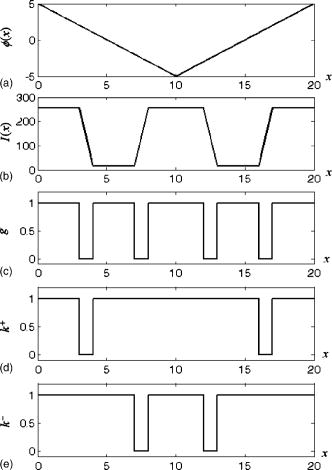
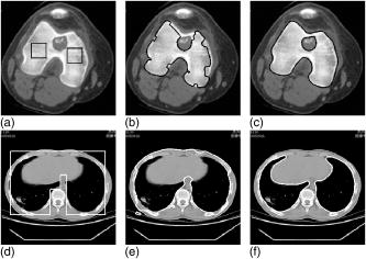
1.IntroductionSince their introduction by Kass ,1 active contours have become very popular for applications in image processing and computer vision. According to the representation of active contours, they can be generally classified into two categories, the explicit active contours1, 2, 3, 4, 5, 6 represented by point sets or B-splines and the implicit active contours7, 8, 9, 10, 11, 12, 13 represented by level set functions. The implicit active contours are superior to the explicit active contours in terms of automatically handling topological changes. Most active contours use the magnitude of the image gradient only in image segmentation. Recently, the directional information of the image gradient has been utilized by some explicit active contours3, 4, 5 to address the issue that the active contour may get confused in image segmentation and converge to the wrong edge when multiple edges with different directions are present near the object boundary. Although some literature11, 12 on implicit active contours has considered the importance of the gradient directional information, none of them emphasizes the above-mentioned issue. In this paper, based on the original geodesic active contour,9, 10 which is a typical implicit active contour, a novel active contour model called the directional geodesic active contour is proposed by incorporating the gradient directional information into the geodesic active contour model. Experiments show that the proposed active contour performs better than the geodesic active contour in image segmentation when multiple edges with different image gradient directions are present near the object boundary to confuse the active contour. 2.Geodesic Active ContourLet be a given gray-scale image. The geodesic active contour9, 10 as an evolving curve is denoted by and represented by the zero level set of a level set function , i.e., . The level set function is normally selected to be a signed distance function that is negative in the interior and positive in the exterior of the zero level set. The evolution of the geodesic active contour embedded in the level set function can be formulated by the following partial differential equation: where is a constant parameter controlling the balloon force, and is the edge indicator function, which is commonly defined bywhere denotes the Gaussian filter with standard deviation . With an appropriate initialization, the evolving curve represented by the zero level set of the level set function will stop at the desired edges where the function is approximated to zero.3.Directional Geodesic Active ContourSince the geodesic active contour performs the object segmentation essentially by detecting the edges formed at the object boundary, the edge indicator function plays a very important role in the object segmentation. It is seen from Eq. 2 that the edge indicator function is derived from the image gradient that consists of the gradient magnitude and the gradient direction. However, only the gradient magnitude is used in the function and the gradient direction is discarded. The function will be approximated to 0 at the edge location regardless of its corresponding gradient direction, and to 1 in other places. Therefore, it can only detect the presence of an edge but cannot discern the associated gradient direction of the edge. When multiple edges are present near the object boundary, the geodesic active contour that employs the function may get confused about which is the right edge since all edges have a large gradient magnitude, and may be attracted by the wrong edges instead of the desired object boundary. In order to prevent the geodesic active contour from being attracted by the wrong edges, we propose incorporating the image gradient direction in the edge indicator function. Here is how we distinguish a desired edge from other undesired edges. An edge is considered desired if its corresponding gradient direction is consistent with the gradient direction of the object edge, i.e., the angle between the two gradient directions is no more than . Otherwise, the edge will be considered undesired. Since the object edge is unknown at the beginning, in determining whether an edge is desired, we use the gradient direction of the level set function to replace the gradient direction of the object edge. We can do so because the zero level set of the level set function is generally initialized near the object boundary and will conform to the object boundary ultimately, and the object edge’s gradient direction will be either identical or opposite to the gradient direction of the level set function when the zero level set superposes on the object boundary. Based on the above analysis, we propose a modified edge indicator function where the function is defined according to gradient directions of the image and the level set function and is used to tell if an edge is desired.For the definition of the function , we choose the convention that the signed distance function for is negative in the interior and positive in the exterior. When the object to be segmented is darker (i.e., has a lower gray value) than the surrounding background, the following function is used: where denotes the Heaviside function, which takes 1 if and 0 if . On the contrary, when the object is brighter than the surrounding background, the function is defined asThe above definitions of the function can indicate whether an edge is desired by measuring the angle between the gradient direction of the edge (denoted by ) and the gradient direction of the level set function (denoted by ). Based on Eq. 4, if (meaning that the edge is desired) and otherwise. Correspondingly, if we substitute the value of into Eq. 3, the modified edge indicator function will be approximated to 0 at the location of the desired edge since and the gradient is large, and will have the value of 1 at those edge locations with undesired directions since . Note that the function is also approximated to 1 in flat areas due to the small gradient. Therefore, if we use the novel edge indicator function in the geodesic active contour model, the evolving curve will stop at the desired edge only.Fig. 1 illustrates the difference between the traditional edge indicator function and the modified edge indicator function in 1-D format. It can be seen that all four edges are detected by the traditional edge indicator function regardless of their directions, while only those two edges with the same gradient direction as the level set function are detected by the modified edge indicator function formulated by Eqs. 3, 4. Similarly, the modified edge indicator function formulated by Eqs. 3, 5 only detects the two edges with opposite gradient direction to that of the level set function. Therefore, the modified edge indicator function can selectively detect the desired image edges. Fig. 1Comparison between the traditional and the modified edge indicator functions: (a) the level set function at a given time; (b) the image intensity ; (c) the traditional edge indicator function ; (d) the modified edge indicator function formulated by Eqs. 3, 4 (denoted by ); (e) the modified edge indicator function formulated by Eqs. 3, 5 (denoted by ).  By replacing the function in Eq. 1 with the function , we can obtain a modified geodesic active contour model, referred to as the directional geodesic active contour, with the following evolution equation: Based on the property of the edge indicator function , the directional geodesic active contour can avoid being attracted by the edges with undesired gradient directions.4.Experimental ResultsExperiments have been conducted on some synthetic and real images to compare the performance of the directional geodesic active contour with that of the traditional geodesic active contour. Here we present two experimental results tested on real images. The upper row of Fig. 2 shows the segmentation of the femur computed tomography (CT) image by the traditional geodesic active contour and the directional geodesic active contour, respectively, under outward balloon force. In this experiment, since the object is brighter than the nearby background, we choose Eqs. 3, 5 to compute the edge indicator function . The lower row of Fig. 2 shows the segmentation of the lung CT image by the two active contour models, respectively, under inward balloon force. Since the object is darker than the background in this image, Eqs. 3, 4 are used in computing the function . It can be observed from Fig. 2 that in both images there exist some edges with undesired gradient directions near the true object boundary. In both cases, the traditional geodesic active contour is wrongly attracted by the edges with undesired gradient directions, while the directional geodesic active contour can move across the undesired edges and correctly conform to the desired boundaries. Fig. 2Tests on real images: (a) the original femur CT image with the initial contour; (b) and (c) the segmentation results of the femur CT image by the traditional geodesic active contour and the directional geodesic active contour, respectively; (d) the original lung CT image with the initial contour; (e) and (f) the segmentation results of the lung CT image by the traditional geodesic active contour and the directional geodesic active contour, respectively.  5.ConclusionBased on the geodesic active contour, we have proposed a directional geodesic active contour that can selectively detect the image edges with different image gradient directions. Experiments conducted on image segmentation show that the directional geodesic active contour is superior to the geodesic active contour when multiple edges with different image gradient directions are present near the object boundary to confuse the active contour. AcknowledgmentThe authors would like to thank the anonymous reviewers for their valuable comments and suggestions. referencesM. Kass, A. Witkin, and D. Terzopoulos,
“Snakes: active contour models,”
Int. J. Comput. Vis., 1 321
–331
(1988). https://doi.org/10.1007/BF00133570 Google Scholar
C. Xu and J. L. Prince,
“Snakes, shapes, and gradient vector flow,”
IEEE Trans. Image Process., 7 359
–369
(1998). https://doi.org/10.1109/83.661186 Google Scholar
H. W. Park, T. Schoepflin, and Y. Kim,
“Active contour model with gradient directional information: directional snake,”
IEEE Trans. Circuits Syst. Video Technol., 11 252
–256
(2001). https://doi.org/10.1109/76.905991 Google Scholar
M. Jacob, T. Blu, and M. Unser,
“Efficient energies and algorithms for parametric snakes,”
IEEE Trans. Image Process., 13 1231
–1244
(2004). https://doi.org/10.1109/TIP.2004.832919 Google Scholar
J. Cheng and S. W. Foo,
“Dynamic directional gradient vector flow for snakes,”
IEEE Trans. Image Process., 15 1563
–1571
(2006). Google Scholar
G. Zhu, Q. Zeng, and C. Wang,
“Simultaneously improving the global and local properties of virtual electric field,”
Electron. Lett., 42 967
–968
(2006). https://doi.org/10.1049/el:20060987 Google Scholar
V. Caselles, F. Catte, T. Coll, and F. Dibos,
“A geometric model for active contours in image processing,”
Numer. Math., 66 1
–31
(1993). https://doi.org/10.1007/BF01385685 Google Scholar
R. Malladi, J. A. Sethian, and B. C. Vemuri,
“Shape modeling with front propagation: a level set approach,”
IEEE Trans. Pattern Anal. Mach. Intell., 17 158
–175
(1995). https://doi.org/10.1109/34.368173 Google Scholar
S. Kichenesamy, A. Kumar, P. Olver, A. Tannenbaum, and A. Yezzi,
“Conformal curvature flows: from phase transitions to active contours,”
Arch. Ration. Mech. Anal., 134 275
–301
(1996). https://doi.org/10.1007/BF00379537 Google Scholar
V. Caselles, R. Kimmel, and G. Sapiro,
“Geodesic active contours,”
Int. J. Comput. Vis., 22 61
–79
(1997). https://doi.org/10.1023/A:1007979827043 Google Scholar
A. Vasilevskiy and K. Siddiqi,
“Flux maximizing geometric flows,”
IEEE Trans. Pattern Anal. Mach. Intell., 24 1565
–1578
(2002). Google Scholar
R. Kimmel and A. M. Bruckstein,
“Regularized Laplacian zero crossings as optimal edge integrators,”
Int. J. Comput. Vis., 53 225
–243
(2003). Google Scholar
G. Zhu, Q. Zeng, and C. Wang,
“Dual geometric active contour for image segmentation,”
Opt. Eng., 45 080505
(2006). https://doi.org/10.1117/1.2333566 Google Scholar
|

